1. Drive shaft system
1. Propeller shaft
Front propeller shaft
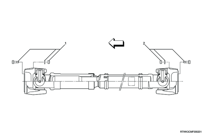
Legend
- Bolt, nut, and washer (Front drive axle side)
- Bolt, nut, and washer (Transfer side)
Rear propeller shaft (Two-piece type)
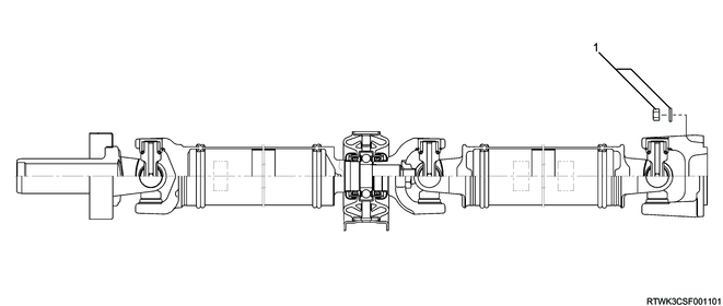
Legend
- Nut and washer
Rear propeller shaft (One-piece type)
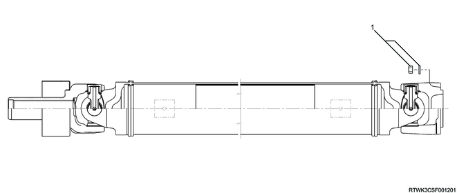
Legend
- Nut and washer
1) Phasing
The propeller shaft is designed to be assembled together with the yoke lug (ears). Through this design, smooth movement of the shaft known as phasing is achieved.
Vibration is caused by asynchronous movement of the propeller shaft. The propeller shaft lowers every time the universal joint rotates. This vibration is similar to the example of a person waving a rope vertically, and watching the resulting wave move to the end of the rope.
Synchronous movement of the propeller shaft is similar to the example of two people each holding the end of a rope wave it vertically at the same time and see the generated waves canceled each other out. This phenomenon is the same as the propeller shaft on the universal joint. The smooth power flow of the drive line is provided by canceling the vibration completely.
In order to ensure the correct installation position, it is important to place alignment marks when removing the propeller shaft.
2) Universal joint
A universal joint consists of 2 Y-shape yokes connected by a spider.
This spider is cross-shaped. The universal joint is designed to handle various loads during acceleration, as well as the effects of the front or rear axle wind-up. The universal joint operates efficiently and safely within the designed angle range.
The bearing used in the universal joint is a needle roller type. The needle roller is kept on the trunnion by a round-shaped bearing cup. The bearing cup is kept in the yoke by a snap ring.
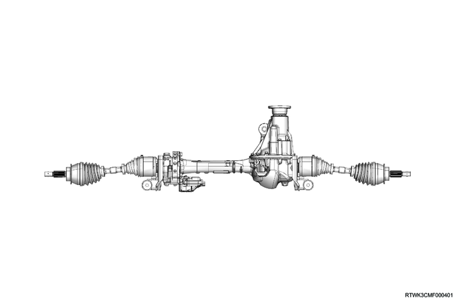
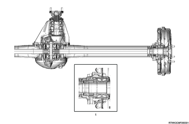
2. Front drive axle
3. Rear axle
The rear axle is semi-floating type, so the vehicle weight is applied to the axle housing.
The center line of the pinion gear is located lower than the center line of the ring gear (hypoid gear).
All components required to transmit power from the propeller shaft to the rear wheels are stored in the BANJO-shaped axle housing.
The (φ220 mm {8.66 in}) ring gear uses a conventional set of a ring gear and pinion gear to transmit the engine driving force to the rear wheels. This gear set transmits the driving force from the propeller shaft to the drive shaft at a 90 degree angle.
The axle shaft is supported with the wheel end of the shaft by the double taper roller bearing. This pinion gear is supported by 2 taper roller bearings. The depth of the pinion is determined by the end of the pinion gear and the shim pack located between the roller bearings pressed on the pinion. The pinion bearing preload is set by compressing a collapsible type spacer between the bearings in the axle housing.
The ring gear is held on the differential cage with 12 bolts.
The differential cage is supported in the axle housing by 2 taper roller bearings. The differential gear and ring gear are installed in relation to the pinion with the selected shim and spacer between the bearing and the differential cage. To move the ring gear, remove shims from one side, and add the same amount to the other side. These shims are used to preload the bearing, and they are compressed on the differential cage. 2 bearing caps are used to retain the differential in the rear axle housing.
This differential is used to rotate the wheels at different speeds while the rear axle continues transmitting the driving force. This prevents tire wear at cornering and early wear on the internal axle parts.
This rear axle is sealed by pinion seals located at the end of each axle shaft with liquid gasket between the differential carrier and the axle housing.
Legend
- ABS specifications
4. Rear differential (Differential lock)
The cam ring and side gear have a dog clutch structure.
The cam ring is engaged with the side gear to lock the rear differential by flowing a current into the coil assembly.
When the differential lock is unlocked, the cam ring is disengaged from the side gear by return spring tension.
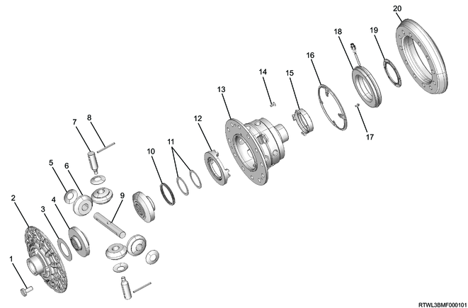
Legend
- Bolt
- Differential cage A
- Thrust washer
- Side gear
- Pinion washer
- Pinion gear
- Pinion shaft S
- Lock pin
- Pinion shaft L
- Return spring
- Thrust washer
- Cam ring
- Differential cage B
- Screw bolt
- Plunger
- Position plate
- Bolt
- Coil assembly
- Solenoid washer
- Ring gear
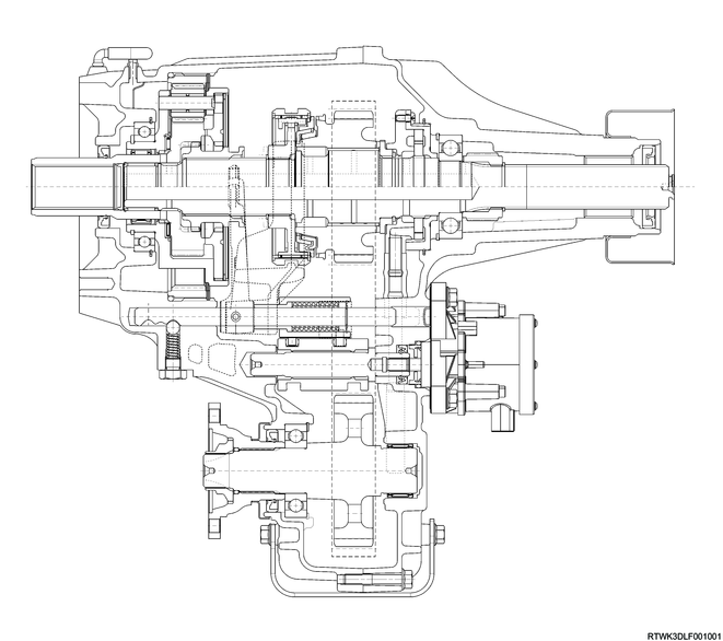
2. Transfer
The transfer case is used to transmit power flow to the front axle. The transfer case provides improved fuel economy and a quieter drive when driving the vehicle on sealed roads that do not require four-wheel drive, by providing a means to shut off power to the front axle. Furthermore, the transfer case provides additional gear reduction when the gear is in low range. This is helpful when encountering difficult off-road conditions.
Use the 4WD switch in the center cluster panel or center console to select the driving range. The 4WD indicator light illuminates when 4WD is selected.
3. Transfer case control system overview
1. System overview
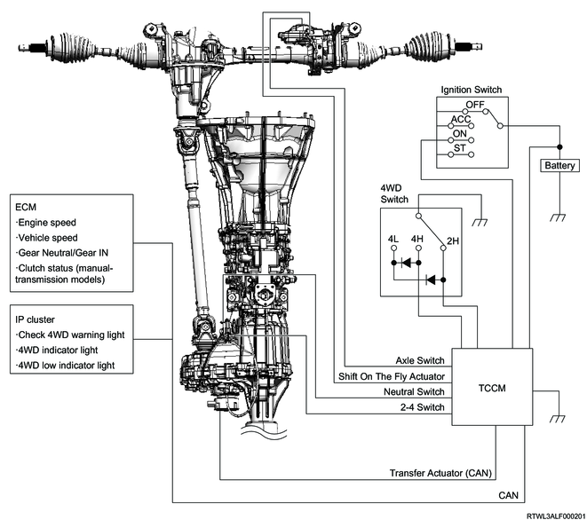
The transfer case control system performs switching between two-wheel drive and four-wheel drive. In addition, there are two modes, High and Low, in four-wheel drive that can be selected according to driving conditions. The shift-on-the-fly system is equipped to perform switching between two-wheel drive and four-wheel drive even while the vehicle is running.
2. 4WD switch operation and conditions for drive system switching
When the following conditions are met, the TCCM switches the transfer drive range from 2H to 4H, or 4H to 2H.
- The vehicle speed is 100 km/h {62 mph} or less.
- The 4WD switch is operated from the 2H position to the 4H position, or from the 4H position to the 2H position.
When the following conditions are met, the TCCM switches the transfer drive range from 4H to 4L, or 4L to 4H.
- 3 km/h {1 mph} or less
- The shift lever is in the N position or the clutch pedal is depressed (Manual transmission models)
- The selector lever is in the N position (Automatic transmission models)
- The 4WD switch is operated from the 4H position to the 4L position, or from the 4L position to the 4H position.
Note
- When switching the 4WD switch from the 4H position to the 4L position and from the 4L position to the 4H position, do so while pushing in the switch.
4. Shift-on-the-fly system overview
The shift-on-the-fly system operates the shift-on-the-fly actuator based on the electrical signals from the TCCM, if the driver switches the 4WD switch from two-wheel drive to four-wheel drive, or from four-wheel drive to two-wheel drive. The shift-on-the-fly actuator connects or shuts off the power to the front axle.
5. Transfer case control components
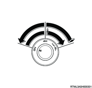
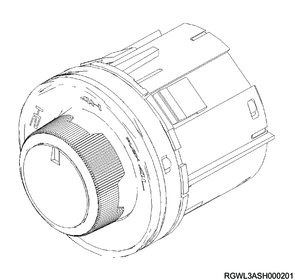
1. 4WD switch
The 4WD switch is for the purpose of allowing the driver to switch between 2H, 4H, and 4L. The installation position varies depending on the type of vehicle.
The 2H signal circuit turns ON when the 4WD switch is at the 2H position, and the TCCM recognizes that the 4WD switch is at the 2H position. The 4H signal circuit turns ON when the 4WD switch is at the 4H position, and the TCCM recognizes that the 4WD switch is at the 4H position. Both the 2H signal circuit and 4H signal circuit turn ON when the 4WD switch is at the 4L position, and the TCCM recognizes that the 4WD switch is at the 4L position.
Pin alignment and circuit diagram
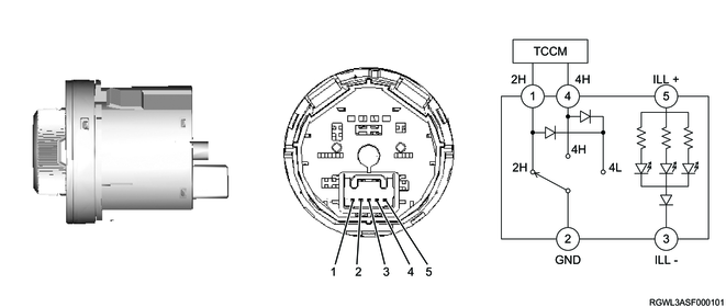
Legend
- 2H signal
- Ground
- Illumination (Ground)
- 4H signal
- Illumination (Power supply)
2. TCCM
The TCCM controls the transfer case control system. The TCCM detects the 2H-4H-4L position of the 4WD switch operated by the driver, then operates the transfer actuator, shift-on-the-fly actuator, and indicator in the instrument panel cluster. In the case of a system malfunction, the failsafe function operates.
3. Transfer actuator
The transfer actuator is installed to the transfer case and performs switching between two-wheel drive and four-wheel drive, and between High and Low independently. The actuator is connected to the shift drum. When the shift drum rotates, the guide roller secured to each shift rod moves along the groove on the shift drum. Therefore, the shift rod moves to the determined position according to the shift drum rotation, and switches the transfer status.

Legend
- Transfer actuator
- Shift drum
- Guide roller
- 2WD - 4WD arm and shift rod assembly
- High - low arm and shift rod assembly
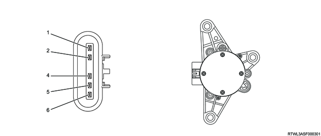
| Terminal No. |
Signal name |
| 1 |
Battery voltage |
| 2 |
Ignition voltage |
| 3 |
- |
| 4 |
CAN High |
| 5 |
CAN Low |
| 6 |
Ground |
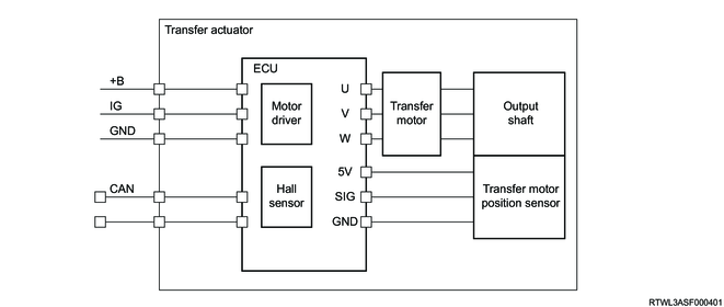
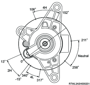
The actuator is comprised of the ECU, motor, and motor position sensor. The motor position sensor is a magnetic sensor, and it detects the output shaft angle and converts it to voltage.
| 2H |
2H-4H |
4H |
4H-Neutral |
Neutral |
Neutral-4L |
4L |
|||
| Transfer motor position |
-15 ≤ θ < 13 |
13 ≤ θ < 106 |
106 ≤ θ < 152 |
152 ≤ θ < 211 |
211 ≤ θ < 258 |
258 ≤ θ < 317 |
317 ≤ θ < 340 |
||
| 4WD SW |
OFF |
OFF |
OFF/ON |
ON |
ON |
ON |
ON |
ON |
ON |
| Axle SW |
OFF |
OFF |
OFF |
ON |
ON |
ON |
*OFF |
ON |
ON |
| Transfer Neutral SW |
OFF |
OFF |
OFF |
OFF |
OFF/ON |
ON |
ON |
OFF/ON |
OFF |
* OFF condition: only when the transfer actuator stops in N
4. Neutral switch
The neutral switch is installed to the transfer case and detects whether the transfer is in the neutral status. The switch contact position turns ON when it is depressed. When the TCCM detects that the neutral switch is ON, it determines that the transfer is in the neutral status.
5. 2-4 switch
The 2-4 switch is installed to the transfer case and detects the transfer operation status. The switch contact point turns OFF when it is depressed. If the TCCM detects that the 2-4 switch is ON, it determines that the transfer is 4H or 4L.
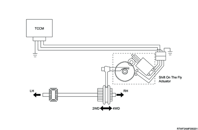
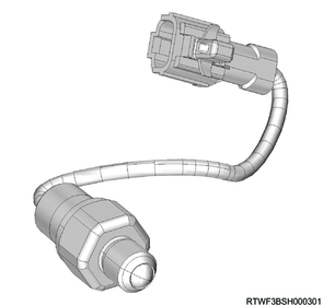
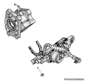
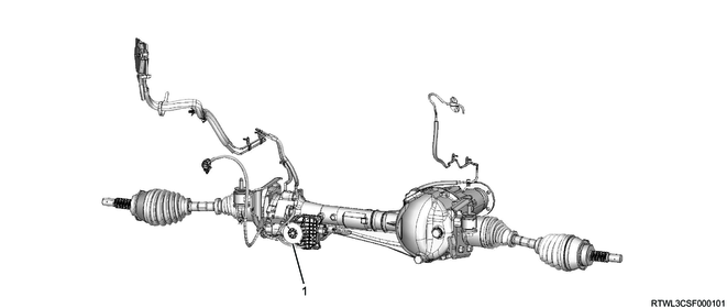
6. Shift-on-the-fly actuator
The shift-on-the-fly actuator is installed to the right side of the front axle case, and performs switching between two-wheel drive and four-wheel drive. The worm gear connected to the actuator rotates in the clockwise or counterclockwise direction by the TCCM changing the direction of current flowing to the actuator drive circuit. The shift rod moves according to the worm gear rotation, and two-wheel drive or four-wheel drive is switched via sleeve. The axle switch is built into the shift-on-the-fly actuator, and current shift-on-the-fly actuator driving conditions from the axle switch are recognized by the TCCM.
7. Check 4WD warning light
The check 4WD warning light notifies the driver of a transfer control system malfunction. The check 4WD warning light normally illuminates when the ignition switch is turned ON, and then turns OFF after approximately 3 seconds. The check 4WD warning light is illuminated, if the TCCM sets a DTC.
8. 4WD indicator light
The 4WD indicator light illuminates when 4H or 4L is selected by the 4WD switch. The light flashes while the transfer actuator shifts from 2H to 4H. After completing the selection to 4H, the light changes to illumination. It continues to illuminate while switching from 4H to 4L. If selection of the desired position is not possible, the indicator light flashes rapidly and the warning buzzer sounds to notify the driver.
9. 4WD low indicator light
The 4WD low indicator light illuminates when 4L is selected by the 4WD switch. The light flashes while the transfer actuator shifts from 4H to 4L. After completing the selection to 4H, the light changes to illumination. If selection of the desired position is not possible, the indicator light flashes rapidly and the warning buzzer sounds to notify the driver.
6. Transfer case control component views
Legend
- Shift-on-the-fly actuator
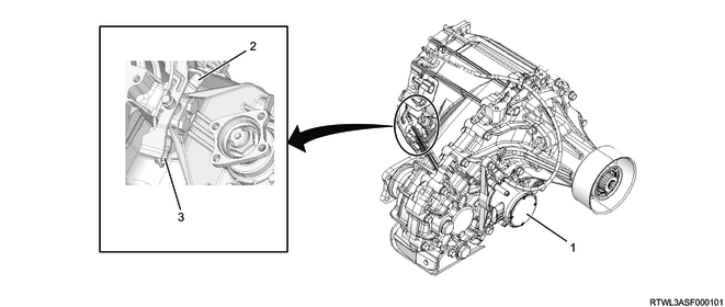
Legend
- Transfer actuator
- 2-4 switch
- Neutral switch
Note
- The illustration shows an RHD model.
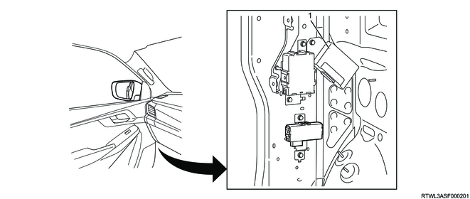
Legend
- TCCM
Legend
- 4WD switch
1. Transfer components
The transfer consists of the following components.
Legend
- Transfer chain
- Front output shaft
- 2WD-4WD shift arm and shift rod
- High-Low arm and shift rod
- Sun gear input shaft
- Carrier and gear assembly
- Planetary dogteeth
- High - low sleeve
- 2WD - 4WD sleeve
- Oil pump
- Transfer main shaft
- Shift drum
- Transfer actuator
7. Differential lock control system overview
The differential lock control system has the following controls and functions.
- Differential lock control
- Information function
- CAN communication function
- Self-diagnosis function
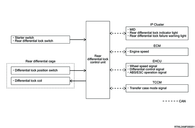
8. Differential lock control system
1. Differential lock control
The differential lock is used to securely transmit driving force under a slippery condition, such as a muddy road or sandy place. When the differential lock is operated, the left and right drive axes are directly connected, and the differential function of the differential is restricted.
1) Operating conditions
When all the following conditions are met, the rear differential lock control unit operates the differential lock.
- The rear differential lock switch is ON.
- 4L mode
- The vehicle speed is 8 km/h {5 MPH} or less.
2) Cancellation condition
When any of the following condition is met, the rear differential lock control unit releases the differential lock.
- The rear differential lock switch is OFF.
- Except 4L mode
- The vehicle speed is 30 km/h {17 MPH} or more.
3) Operation description
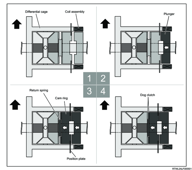
Legend
- When the operation conditions are met, the rear differential lock control unit drives the differential lock coil.
- When the differential lock coil is driven, the plunger inside the differential lock coil is moved to the cam ring side.
- The plunger pushes and shrinks the return spring via the cam ring.
- When the cam ring is moved further, the dog clutches provided to the cam ring and the side gear are engaged.
Note
- The cam ring and the differential cage rotate as a set.
2. Information function
The rear differential lock control unit informs the driver of the operating status or malfunctions of the differential lock control system via the instrument panel cluster.
3. CAN communication function
The rear differential lock control unit sends and receives information with other control units and a scan tool via CAN (Controller Area Network) communication.
4. Self-diagnosis function
If the rear differential lock control unit detects a malfunction relating to the differential lock control system, a DTC is set.
9. Differential lock controls components
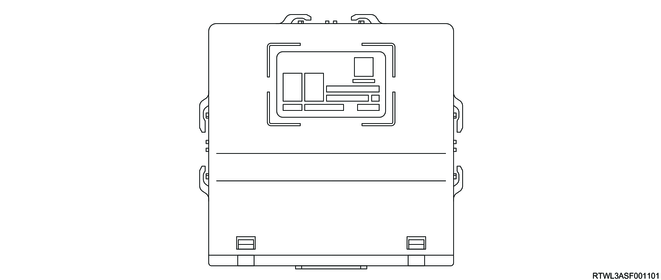
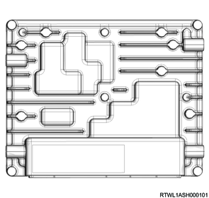
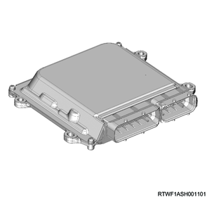
1. Rear differential lock control unit
The rear differential lock control unit controls the differential lock control system based on the information input from the switch and other control units.
Note
- When replacing the rear differential lock control unit, VIN programming is necessary.
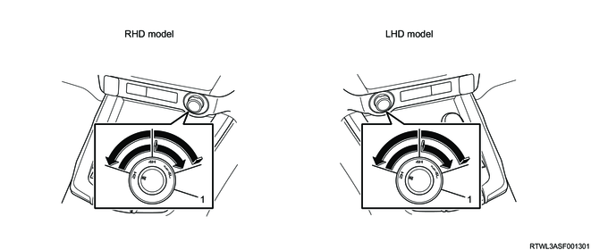
2. Rear differential lock switch
The rear differential lock switch is used by the driver to switch the differential lock between activation and deactivation. Because the rear differential lock switch is a momentary switch, the contact point is closed only while the switch is being depressed.
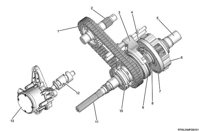
3. Differential lock assembly
The differential lock assembly is installed to the differential carrier.

Legend
- Rear axle case
- Differential lock position switch
- Intermediate connector
- Differential carrier
- Differential lock coil
- Differential lock assembly
1) Differential lock position switch
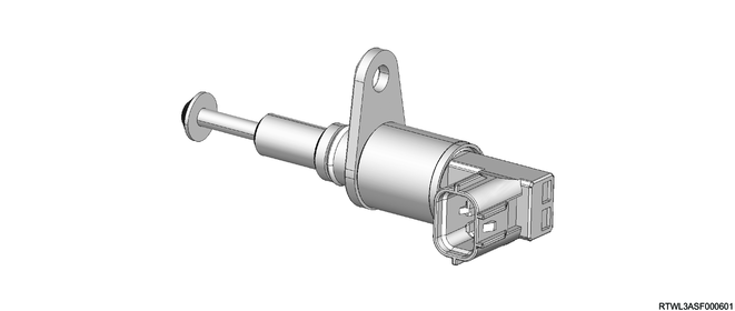
The differential lock position switch is installed to the differential carrier. The differential lock position switch determines the operating status of the differential lock from the position of the position plate installed to the cam ring. The differential lock position switch is set to ON (contact point becomes closed) when the differential lock is activated, and it is set to OFF (contact point becomes open) when the differential lock is deactivated.

Legend
- Final drive
- Differential lock assembly
- Position plate
- Differential lock position switch
2) Differential lock coil

The differential lock coil is installed to the differential cage. The differential lock coil is controlled by the rear differential lock control unit. The rear differential lock control unit drives the differential lock coil when the differential lock is in operation.
4. Multi-Information Display (Models with MID)
The multi-Information display is installed at the center of the instrument panel cluster. The multi-information display informs the driver of information related to the differential lock control system based on the commands from the rear differential lock control unit.
1) When the differential lock is in operation

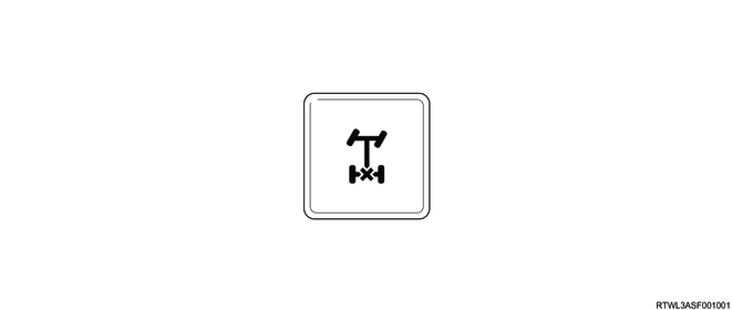
5. Rear differential lock indicator light
The rear differential lock indicator light informs the driver of the control status of the differential lock control system. The rear differential lock indicator light normally illuminates when the ignition switch is turned ON, and then turns OFF after approximately 3 seconds. The rear differential lock control unit illuminates the rear differential lock indicator light when the differential lock is operated. When the differential lock control starts or when the rear differential lock switch is turned ON while the differential lock operating conditions are not met, the rear differential lock control unit flashes the rear differential lock indicator light.

6. Rear differential lock failure warning light
The rear differential lock failure warning light informs the driver of malfunctions in the differential lock control system. The rear differential lock failure warning light normally illuminates when the ignition switch is turned ON, and then turns OFF after approximately 3 seconds. When the rear differential lock control unit detects a DTC, the rear differential lock failure warning light is illuminated.

7. ECM
The ECM sends the engine speed signal information to the rear differential lock control unit via CAN communication.
4JJ3 engine models
RZ4E-TC engine models
8. TCCM
The TCCM sends Transfer case mode information to the rear differential lock control unit via CAN communication.
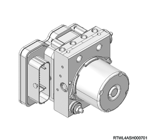
9. EHCU
The EHCU sends the wheel speed signal information and the operation information of the ABS and ESC to the rear differential lock control unit via CAN communication.
10. Differential lock controls component views
Legend
- Rear axle case
- Differential lock position switch
- Intermediate connector
- Differential carrier
- Differential lock coil
- Differential lock assembly
RHD models

Legend
- Rear differential lock control unit
LHD models

Legend
- Rear differential lock control unit
Manual transmission models

Legend
- Rear differential lock switch
Note
- The illustration shows an RHD model.
Automatic transmission models
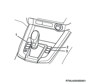
Legend
- Rear differential lock switch
- Hill descent control switch (Models equipped with ESC)
- Parking aid system OFF switch
Note
- The illustration shows an RHD model.
11. Power transmission
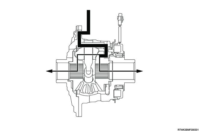
1. Power transmission (Differential lock)
The power is delivered as follows, according to switching the rear differential lock switch ON/OFF.
1) Free status

2) When the left tire skids.
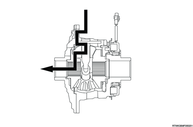
3) Lock status
2. Power transmission (Transfer)
The power delivered by the transfer is as follows, according to the 4WD switch position.
1) 4WD switch - 2H
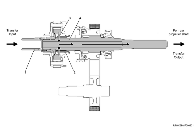
Legend
- Sun gear input shaft
- High - low sleeve
- Constant velocity
- Transfer main shaft
2) 4WD switch - 4H
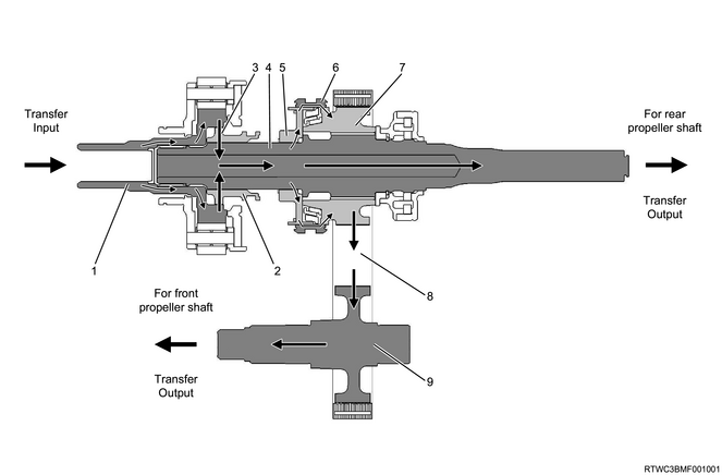
Legend
- Sun gear input shaft
- High - low sleeve
- Constant velocity
- Transfer main shaft
- 2WD-4WD clutch hub
- 2WD - 4WD sleeve
- Drive sprocket
- Transfer chain
- Front output shaft
3) 4WD switch - 4L
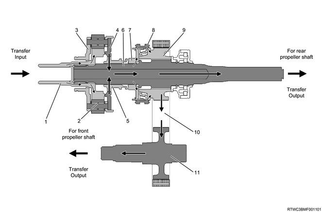
Legend
- Sun gear input shaft
- Deceleration
- Carrier and gear assembly
- Planetary dogteeth
- High - low sleeve
- Transfer main shaft
- 2WD-4WD clutch hub
- 2WD - 4WD sleeve
- Drive sprocket
- Transfer chain
- Front output shaft
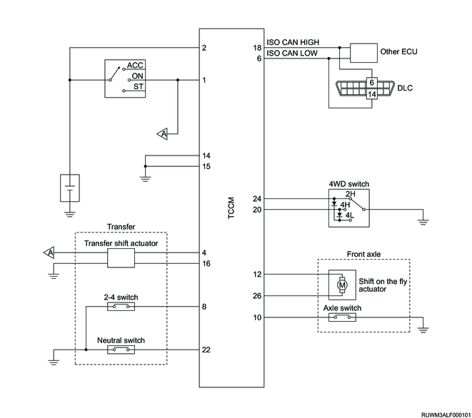
12. General circuit diagram
1. TCCM schematic circuit diagram
2. TCCM outline view and connector pin layout
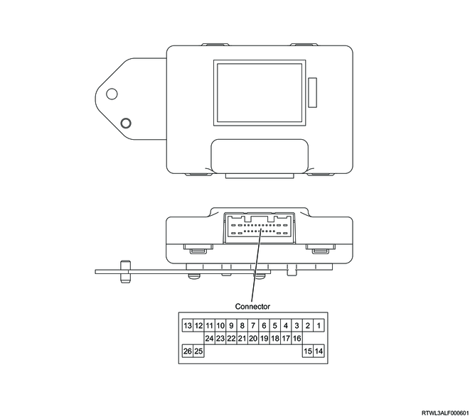
| Terminal No. |
Signal name |
| 1 |
Ignition voltage |
| 2 |
Battery voltage |
| 3 |
- |
| 4 |
CAN2 High |
| 5 |
- |
| 6 |
CAN1 Low |
| 7 |
- |
| 8 |
2-4 switch |
| 9 |
- |
| 10 |
Axle switch |
| 11 |
- |
| 12 |
Shift-on-the-fly actuator drive signal A |
| 13 |
- |
| 14 |
Ground |
| 15 |
Ground |
| 16 |
CAN2 Low |
| 17 |
- |
| 18 |
CAN1 High |
| 19 |
- |
| 20 |
4WD switch signal 4H |
| 21 |
- |
| 22 |
Transfer neutral switch |
| 23 |
- |
| 24 |
4WD switch signal 2H |
| 25 |
- |
| 26 |
Shift-on-the-fly actuator drive signal B |
3. Rear differential lock control unit general circuit diagram.

4. Rear differential lock control unit outline view and connector pin layout
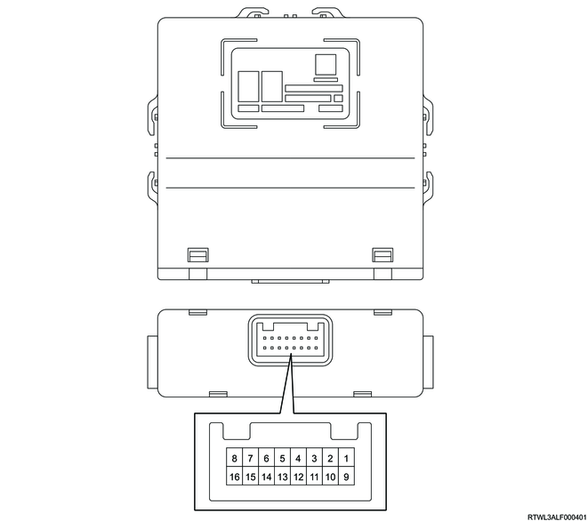
| Pin No. |
Pin function |
| 1 |
CAN (High) |
| 2 |
Ignition power supply |
| 3 |
- |
| 4 |
Rear differential lock switch signal |
| 5 |
- |
| 6 |
- |
| 7 |
Differential lock coil ground |
| 8 |
Differential lock coil control |
| 9 |
CAN (Low) |
| 10 |
Battery power supply |
| 11 |
- |
| 12 |
- |
| 13 |
Differential lock position switch signal |
| 14 |
- |
| 15 |
Ground |
| 16 |
Differential lock coil power supply |