1. Component views
Tire air pressure sensor
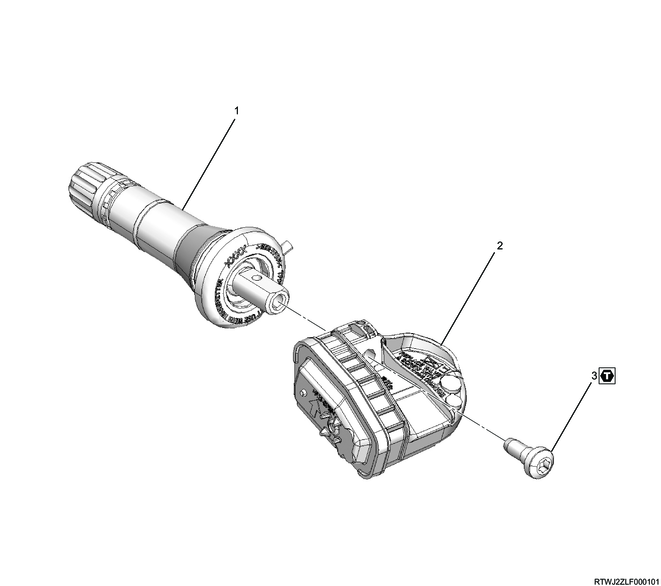
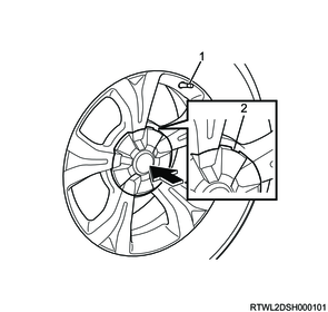
Part name
- Valve
- Tire air pressure sensor
- Screw
Tightening torque
3: 1.4 N・m { 0.14 kgf・m / 12.4 lb・in }
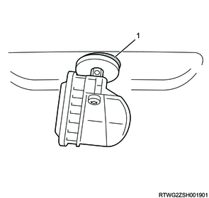
2. Tire air pressure sensor installation
1) Check the production period of the tire air pressure sensor.
Caution
- Do not reuse the tire air pressure sensor and valve.
- Do not use tire air pressure sensors after 12 months or more have passed since production.
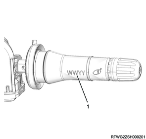
Legend
- Production week and production year markings
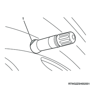
2) Record the 8-digit tire air pressure sensor ID marked on the tire air pressure sensor to be installed.
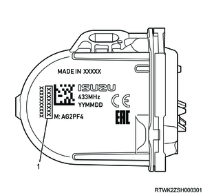
Legend
- 8-digit tire air pressure sensor ID
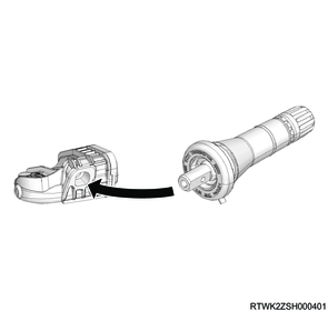
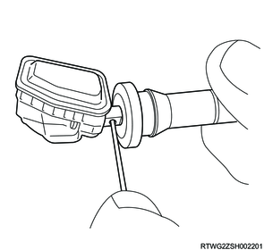
3) Install the tire air pressure sensor to the valve.
Note
- Match the tire air pressure sensor hole shape with the shape of the valve tip.
4) Insert the pin into the valve hole to hold the tire air pressure sensor.
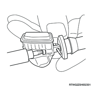
5) Install the tire air pressure sensor to the valve using a T10 Torx screwdriver.
Tightening torque: 1.4 N・m { 0.14 kgf・m / 12.4 lb・in }
Caution
- Do not reuse screws.
- Do not hold the tire air pressure sensor directly by hand.
The Torx screw may become overtightened.
Note
- Tighten until the screw head makes contact with the tire air pressure sensor.
6) Apply water, soapy water, or lubricant to the rubber section of the valve and the upper section of the tire air pressure sensor.
Caution
- If lubricant is applied to valves by soaking, do not soak the tire air pressure sensor in liquid for 24 hours or more.
7) Clean the section around the valve installation hole of the disc wheel.
Note
- Clean and remove any foreign material before installing the valve.
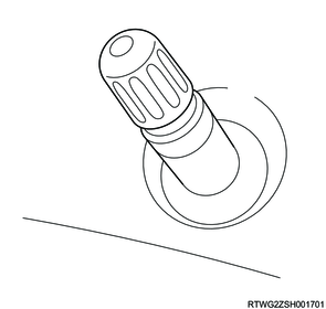
8) Insert the valve straight into the valve installation hole of the disc wheel, and install a suitable tool.
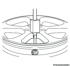
Caution
- Do not install tire air pressure sensors to unapproved disc wheels.
9) Install the valve to the disc wheel using a suitable tool.
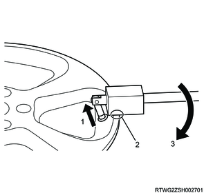
Legend
- Valve travel direction
- Place a suitable tool against the wheel rim.
- Suitable tool force application direction
Note
- Pull the valve straight up and in line with the center of the valve installation hole.
Caution
- Do not apply excessive force when installing the valve.
This may cause damage due to the tire air pressure sensor contacting the wheel rim.
10) Check the installation conditions of the tire air pressure sensor.
Correct tire air pressure sensor installation conditions
The valve is sealed with the wheel rim.
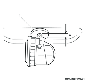
Legend
- The valve lip section is sealed with the wheel rim.
Legend
a. The front surface of the tire air pressure sensor does not make contact with the wheel rim.
The valve and valve installation hole center axis align.
The tire air pressure sensor is installed level with the wheel rim.
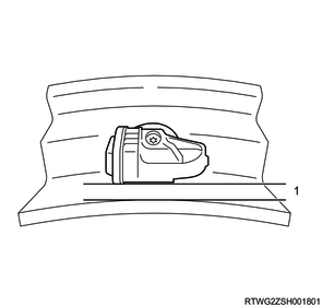
Legend
- Level
The tire air pressure sensor is installed to the wheel rim in the correct direction.
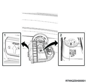
Legend
- Face the arrow marking upward.
- Face the marking upward.
Incorrect tire air pressure sensor installation conditions
The valve is not sealed with the wheel rim.
Legend
- The valve lip section is not sealed with the wheel rim due to an insufficient valve installation.
The valve is caught in the valve installation hole.
Legend
- Because the valve installation angle is not correct, the valve rib section is caught in the valve installation hole.
11) If the valve is not installed correctly, seal the valve with the wheel rim.
Note
- Correct the installation condition within 1 hour.
12) Check again the installation status of the sealed valve.
Caution
- If the cone section of the valve is damaged, do not use it.
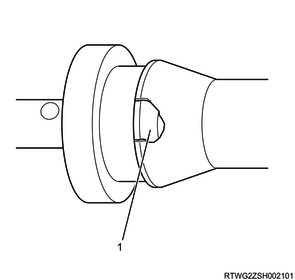
Legend
- Damaged cone section
Caution
- If excessive force is required to seal the valve with the wheel rim, remove the valve.
- If the valve is not installed correctly to the wheel rim, do not install the tire to the disc wheel.
3. Tire installation
Caution
- Install the tires by following the handling instructions provided by each tire changer manufacturer.
- Do not get too close to the tire when inflating it.
- Do not exceed the specified air pressure when inflating the tire.
- Note that if the tire is over-inflated, the tire bead may become cut, resulting in injuries.
- Note that if the tire bead rides over the rim flange and gets cut, it may cause injury.
- If the tire bead is not attached even when the tire is inflated to the specified air pressure, release air, apply lubricant, and inflate it again.
1) Apply tire wax to the tire bead.
2) Set the valve at the 4:30 position against the tire changer attachment.
Note
- To prevent damage to the tire air pressure sensor, set in this position.
Legend
- Valve
Legend
a. 4:30 position
3) Set the lower tire bead to the wheel rim in front of the valve.
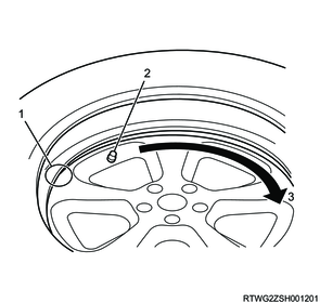
Legend
- Position where the lower tire bead is put on the wheel rim
- Valve
- Wheel rim rotation direction
4) Hold the tire at a 3 o'clock position against the tire changer attachment, and rotate the disc wheel clockwise.
5) Put the lower tire bead into the center of the disc wheel.
Note
- When the disc wheel rotates counterclockwise, hold the tire at a 9 o'clock position against the tire changer attachment.
6) To put the upper tire bead into the disc wheel, set the valve at the 4:30 position against the tire changer attachment once again.
Legend
- Valve
Legend
a. 4:30 position
7) Hold the tire at a 3 o'clock position against the tire changer attachment, and rotate the disc wheel clockwise.
8) Put the upper tire bead into the center of the disc wheel.
Note
- When the disc wheel rotates counterclockwise, hold the tire at a 9 o'clock position against the tire changer attachment.
- The tire bead at the valve position should be put in last.
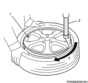
Legend
- Valve
- Attachment
- Wheel rim rotation direction
Note
- Align the matching mark on the wheel to the matching mark on the tire.
- If the matching mark on the wheel wears off, align with the valve.
| Wheel side red paint mark |
Diameter: 10 mm {0.4 in} |
| Tire side red paint mark |
Diameter: 8 mm {0.3 in} |
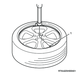
9) Fill the tire with air without the valve core installed to the valve.
Caution
- Do not allow any foreign material to enter the valve.
Note
- Inflate so that the tire bead is completely sealed with the disc wheel.
10) Install the valve core to the valve.
Caution
- Do not reuse the valve core.
Tightening torque: 0.45 N⋅m {0.045 kgf⋅m / 3.9 lb⋅in}
11) Adjust the tire air pressure.
12) Install the valve cap to the valve.
4. Disc wheel installation
1. Models with aluminum wheels
1) Temporarily tighten the disc wheel to the vehicle.
2) Lower vehicle.
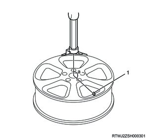
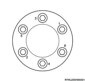
3) Final tighten the wheel nut in the order shown in the diagram.
Tightening torque: 120 N⋅m {12 kgf⋅m / 87 lb⋅ft}
Caution
- After completing installation, make sure to further tighten the wheel nuts to the specified torque after the vehicle has been driven a distance exceeding the standard value.
Standard: 50 to 100 km { 31 to 62 mile }
4) Install the wheel cap to the disc wheel.
Note
- For models with 18-inch aluminum wheels, align the wheel cap groove with the air valve before installing.
5) Check that the surfaces of the wheel cap and wheel are flat.
Note
- If the surfaces are not flat, the wheel cap may fall off.
Legend
- Valve
- Wheel cap groove
2. Models with steel wheels
1) Temporarily tighten the disc wheel and wheel cap to the vehicle.
2) Lower vehicle.
3) Final tighten the wheel nut in the order shown in the diagram.
Tightening torque: 120 N⋅m {12 kgf⋅m / 87 lb⋅ft}
Caution
- After completing installation, make sure to further tighten the wheel nuts to the specified torque after the vehicle has been driven a distance exceeding the standard value.
Standard: 50 to 100 km { 31 to 62 mile }