1. Final drive inspection
1) Inspect each bearing for the following.
- Seizing
- Spalling
- Noise
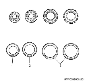
Legend
- Inner bearing
- Outer bearing
- Side bearing
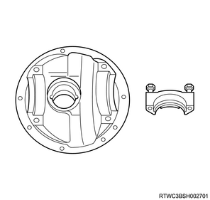
2) Inspect the differential carrier front drive axle mounting sections, differential carrier side bearing mounting sections, as well as the bearing cap for the following.
- Cracking
- Damage
- Wear
3) Inspect the pinion bearing race and pinion bearing oil seal inlay sections for the following.
- Cracking
- Damage
- Wear
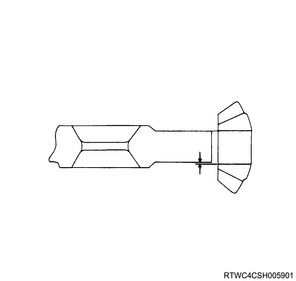
4) Inspect the flange for the following.
- Worn oil seal contact section
- Worn spline section
- Cracking of mounting section
- Damage to the mounting section

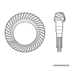
5) Inspect the gear contact surfaces on the forward and reverse sides of the ring gear and drive pinion for the following.
- Chipping
- Cracking
- Spalling
- Pitting
- Improper tooth contact
6) Inspect the spline section of the drive pinion for the following.
- Cracking
- Twisting
- Damage
Caution
- Replace the ring gear and drive pinion as a set.
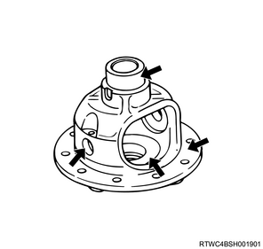
2. Differential cage inspection
1. Visual inspection
1) Inspect the side gear, side gear thrust washer, pinion gear, and cross pin for the following.
- Wear
- Damage
- Other malfunctions
2) Inspect the differential cage for the following.
- Wear
- Damage
- Corrosion
- Other malfunctions
3) Inspect the fitting section of the differential cage and ring gear, the fitting section of the differential cage and side gear, as well as the differential cage cross pin holes for the following.
- Damage
- Roughness
Note
- Repair minor damage and wear using an oil stone or fine sandpaper.
2. Pinion gear measurement
1) Measure the outer diameter of the cross pin using a micrometer.
2) Measure the inner diameter of the pinion gear using a vernier caliper.
3) Calculate the clearance between the pinion and the cross pin from the measured values.
Standard: 0.06 to 0.12 mm { 0.002 to 0.005 in }
Limit: 0.2 mm { 0.008 in }
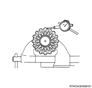
3. Side gear measurement
1) Install the side gear to the drive shaft spline.
2) Measure the looseness of the side gear and drive shaft in the rotational direction using a dial gauge.
Standard: 0.08 to 0.36 mm { 0.003 to 0.014 in }
Limit: 0.5 mm { 0.02 in }
4. Differential cage measurement
1) Measure the outer diameter of the side gear using a micrometer.
2) Measure the inner diameter of the differential cage using a cylinder gauge.
3) Calculate the clearance of the side gear and differential cage from the measured values.
Standard: 0.03 to 0.11 mm { 0.001 to 0.004 in }
Limit: 0.15 mm { 0.006 in }
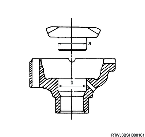
Legend
a. Side gear outer diameter
b. Differential cage inner diameter