1. Crankshaft inspection
1. Cleaning
1) Clean the following parts.
- Crankshaft journal
- Crankshaft lower bearing
- Crankshaft upper bearing
- Crank pin
2. Visual inspection
1) Inspect the crankshaft journal and crank pin for the following.
- Wear
- Damage
- Clogged oil port
2) Inspect the crankshaft lower bearing for the following.
- Wear
- Damage
Note
- Replace the bearing as a set if an abnormal condition is found.
3) Inspect the crankshaft upper bearing for the following.
- Wear
- Damage
Note
- Replace the bearing as a set if an abnormal condition is found.
4) Clean the crankshaft with organic solvent.
Caution
- Thoroughly wipe up any oil from the journal and crank pin.
5) Prepare a test solution (5 to 10% copper chloride ammonium).
Warning
- Do not allow the inspection solution to come in contact with your eyes, hands, clothes, etc.
- If the inspection solution has gotten in your eyes, immediately wash with a large amount of fresh water and seek medical treatment.
6) Apply inspection solution to the journal and crank pin using an oil can.
Caution
- Level the crankshaft.
- Do not allow any inspection solution to adhere near the oil port.
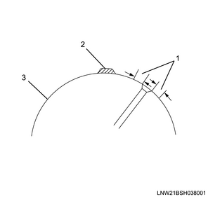
Legend
- Drip prohibited area
- Test liquid drop section
- Pin or journal moving surface
7) Let the inspection solution sit for 30 to 40 seconds before inspecting to see if the color has changed.
Note
- If the inspection solution changed to a copper color, replace the crankshaft.
8) Wipe away the inspection solution from the crankshaft using a cloth, etc., and clean the crankshaft using water, steam, etc.
Caution
- Perform immediately after inspection.
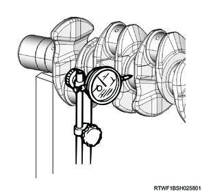
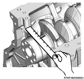
3. Crankshaft runout measurement
1) While slowly turning the crankshaft, measure the runout at the crankshaft center using a dial gauge.
Note
- If the measured value exceeds the limit, replace the crankshaft.
Standard: 0.05 mm or less { 0.0020 in or less }
4. Crankshaft journal and crank pin measurement
Caution
- Because the journal sections and crank pins have undergone soft nitriding (tufftriding) treatment, do not repair by grinding.
1) Referring to the diagram, measure the 4 crankshaft journal locations using a micrometer.
Standard: 57.909 to 57.924 mm { 2.2799 to 2.2805 in } No. 3 journal section
Standard: 57.923 to 57.938 mm { 2.2804 to 2.2810 in } Other than the No. 3 journal
2) Referring to the diagram, measure the 4 crankshaft crank pin locations using a micrometer.
Standard: 50.915 to 50.930 mm { 2.0045 to 2.0051 in } Pin section

5. Oil clearance measurement
1) Install the crankshaft upper bearing to the cylinder block.
2) Install the crankshaft to the cylinder block.
Caution
- Level the crankshaft to install.
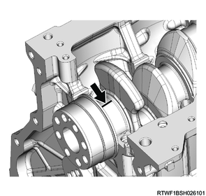
3) Place PLASTIGAUGE on the crankshaft journal.
4) Install the crankshaft lower bearing to the bearing cap.
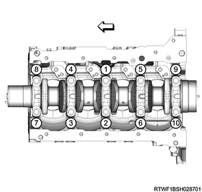
5) Install the bearing caps to the cylinder block in the order shown in the diagram.
Note
- Install so that the bearing cap front mark faces the front of the engine.
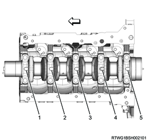
Legend
- No. 1
- No. 2
- No. 3
- No. 4
- No. 5
6) Apply engine oil to the threaded portions and seating surfaces of the bearing cap bolts.
7) Tighten the bearing cap bolts to the cylinder block in the order shown in the diagram.
Caution
- Do not reuse the bearing cap bolt.
However, only when a new bearing cap bolt is used to measure the oil clearance, the bearing cap bolt can be reused. - Carefully place the bearing cap on the cylinder block.
- Do not rotate the crankshaft after tightening the bearing caps.
Tightening torque: 50 N・m { 5.1 kgf・m / 36.9 lb・ft } 1st time
Tightening Angle : 60 to 90 ° 2nd time
8) Remove the bearing cap from the cylinder block.
Caution
- Remove carefully.
9) Measure the widest point of the flattened PLASTIGAUGE, and inspect the oil clearance of the crankshaft journal section.
10) Measure the maximum width portion of the PLASTIGAUGEs crushed by the tightening of the bearing caps.
Note
- Replace all of the crankshaft bearings or the crankshaft if the measured value exceeds the limit.
Standard: 0.030 to 0.056 mm { 0.0012 to 0.0022 in } Other than the No. 3 journal
Standard: 0.044 to 0.070 mm { 0.0017 to 0.0028 in } No. 3 journal
11) Remove any PLASTIGAUGE adhering to the following parts.
- Crankshaft lower bearing
- Crank pin