1. Piston inspection
1. Cleaning
1) Remove any carbon from the following parts.
- Piston head
- Piston ring groove
- Piston ring end gap
Caution
- Do not use a wire brush.
2. Visual inspection
1) Inspect the piston for the following.
- Cracking
- Wear
- Seizing
2) Inspect the connecting rod bearing for the following.
- Wear
- Damage
- Spalling
Note
- Replace the bearings as an assembly if there are abnormal conditions.
3) Inspect the piston pin for the following.
- Crack
- Wear
- Damage
3. Measurement of clearance between cylinder bore and piston
1) Measure the inner diameter of the cylinder bore in the thrust direction and radial direction at the specified positions using a cylinder gauge.
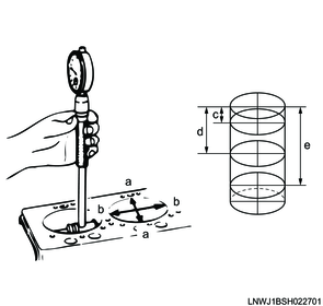
Legend
a. Thrust direction
b. Radial direction
Measurement position
c: 20 mm { 0.787 in } Measurement position from the upper surface of the cylinder block
d: 80 mm { 3.15 in } Measurement position from the upper surface of the cylinder block
e: 140 mm { 5.51 in } Measurement position from the upper surface of the cylinder block
2) Calculate the average measured value excluding the maximum and minimum values.
Standard: 95.421 to 95.450 mm { 3.7567 to 3.7579 in }
3) Measure the piston outer diameter at the measurement position in the diagram, perpendicular to the piston pin.
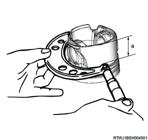
Measurement position
a: 11 mm { 0.43 in } From the bottom surface of the piston
4) Calculate the clearance between the piston and the cylinder bore inner diameter.
Note
- If the measured value is outside the standard range, replace the piston.
Standard: 0.032 to 0.120 mm { 0.0013 to 0.0047 in }
5) Select a piston so that the clearance is the specified value.
Note
- Grades A, B, and C are marked on the top of the piston when shipped from the factory.
| Grade |
Outer diameter |
| A |
95.330 to 95.357 mm { 3.7531 to 3.7542 in } |
| B |
95.340 to 95.369 mm { 3.7535 to 3.7547 in } |
| C |
95.350 to 95.379 mm { 3.7539 to 3.7551 in } |

Legend
- Grade marking
- Last 4 digits of the part number
- Data matrix code
- Front mark
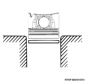
4. Measurement of piston ring joint
1) Insert the piston ring into the cylinder bore.
Note
- Push the piston ring into the cylinder using the piston until the cylinder bore is at the position where it is smallest.
- Push in a right angle to the cylinder wall.
Caution
- Do not decline the piston ring in either direction.
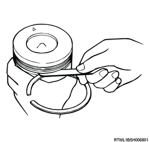
2) Measure the clearance of the ring joint using a feeler gauge.
Note
- If the measured value is outside the standard range, replace the piston ring.
| Piston ring |
Standard value |
| Top ring |
0.32 to 0.46 mm { 0.0126 to 0.0181 in } |
| 2nd ring |
0.42 to 0.66 mm { 0.0165 to 0.0260 in } |
| Oil ring |
0.27 to 0.56 mm { 0.0106 to 0.0220 in } |
5. Measurement of clearance between piston ring and piston ring groove
1) Remove all carbon from the piston ring grooves.
2) Install the piston ring to the piston.
3) Measure the clearance between the piston ring groove and the piston ring using a feeler gauge.
Note
- Top ring cannot be measured, because of its shape.
- Replace the piston or piston ring if the measured value exceeds the limit.
| Piston ring |
Standard value |
Limit |
| Top ring |
- |
- |
| 2nd ring |
0.06 to 0.12 mm { 0.0024 to 0.0047 in } |
0.15 mm { 0.0059 in } |
| Oil ring |
0.03 to 0.07 mm { 0.0012 to 0.0028 in } |
0.15 mm { 0.0059 in } |
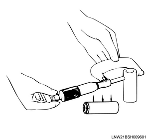
6. Measurement of clearance between piston and piston pin
1) Apply the engine oil to the piston pin.
2) Insert the piston pin to the piston.
3) Inspect whether a certain amount of resistance exists in the piston when the piston pin is lightly pushed.
Note
- Inspect with the piston at room temperature.
- If piston pin can be easily pushed into the piston, measure the clearance between the piston and the piston pin.

4) Measure the outer diameter of the piston pin using a micrometer.
Note
- If the measured value is outside the standard range, replace the piston pin.
Standard: 33.995 to 34.000 mm { 1.3384 to 1.3386 in }
5) Calculate the clearance between the inner diameter of the piston pin hole and the outer diameter of the piston pin.
Note
- Replace the piston or piston pin if the measured value exceeds the standard value.
Standard: 0.008 to 0.019 mm { 0.0003 to 0.0007 in }
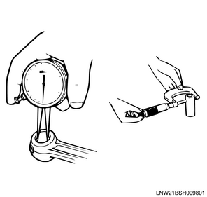
6) Measure the connecting rod small end bushing inner diameter using a dial gauge.
7) Calculate the clearance between the inner diameter of the connecting rod small end bushing and the outer diameter of the piston pin.
Note
- Replace the connecting rod or piston pin if the measured value exceeds the limit.
Standard: 0.008 to 0.020 mm { 0.0003 to 0.0008 in }
Limit: 0.050 mm { 0.0020 in }
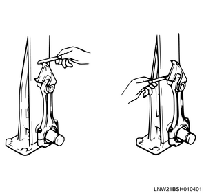
7. Connecting rod measurement
1) Measure the twisting and degree of parallelization of the connecting rod using a connecting rod aligner.
Note
- For a connecting rod alignment of 100 mm {3.94 in}, measure the twist and the degree of parallelization of the large end hole and the small end hole.
- Replace the connecting rod if the measured value exceeds the standard value.
Standard: 0.05 mm { 0.0020 in } Twisting
Standard: 0.05 mm { 0.0020 in } Degree of parallelization
8. Connecting rod oil clearance measurement
1) Remove the connecting rod bearing cap from the connecting rod.
Note
- The removed caps should be lined up in the order of the cylinder number.
2) Clean the bearing and crankshaft pin.
3) Place the PLASTIGAUGE on the crankshaft pin.
4) Apply engine oil to the threaded portions and seating surfaces of the tightening bolts.
5) Temporarily tighten the connecting rod bearing caps and connecting rods to the crankshaft.
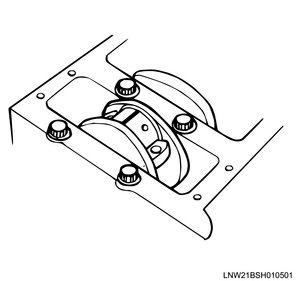
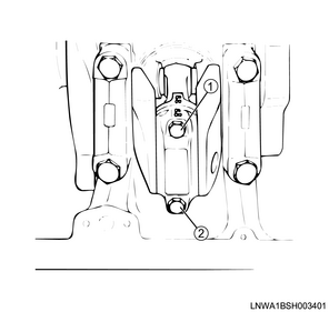
6) Final tighten the tightening bolts in the order shown in the diagram using the special tool.
Caution
- Do not rotate the crankshaft.
Tightening torque: 29.4 N・m { 3.0 kgf・m / 22 lb・ft } 1st time
Tightening Angle : 45 to 60 ° 2nd time
SST: 5-8840-0266-0 - angle gauge
7) Remove the connecting rod bearing cap from the connecting rod.
8) Measure the widest point of the flattened PLASTIGAUGE, and measure the oil clearance of the crank pin section.
Note
- Replace the bearings as a set if the measured value is outside the standard range.
Standard: 0.033 to 0.075 mm { 0.0013 to 0.0030 in }
9) Remove all PLASTIGAUGE from the following parts.
- Connecting rod bearing
- Crank pin