1. Component views
Clutch disc No. 1 and Clutch disc No. 2 assembly
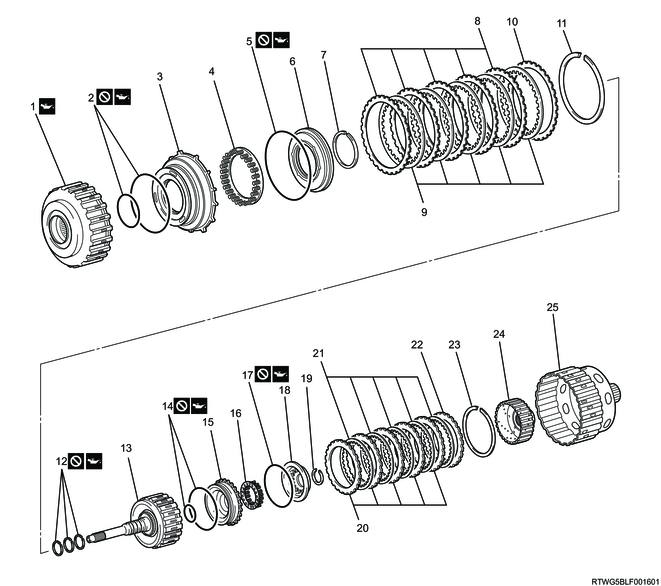
Part name
- No. 2 clutch drum sub-assembly
- O-ring
- Direct clutch piston
- Direct clutch return spring sub-assembly
- O-ring
- Clutch balancer No. 2
- Snap ring
- Clutch plate No. 2
- Clutch disc No. 2
- Clutch flange No. 2
- Snap ring
- Seal ring
- Forward clutch drum sub-assembly
- O-ring
- Forward clutch piston
- Forward clutch return spring sub-assembly
- O-ring
- Clutch balancer No. 1
- Snap ring
- Clutch plate No. 1
- Clutch disc No.1
- Clutch flange No. 1
- Snap ring
- Forward clutch hub
- Clutch hub sub-assembly
2. Direct clutch piston installation
1) Coat the 2 new O-rings with ATF.
Caution
- Do not reuse the O-ring.
2) Install them to the direct clutch piston.
| Inner diameter |
Thickness |
| 74.7 mm { 2.9409 in } |
2.62 mm { 0.1031 in } |
| 121.0 mm { 4.7638 in } |
3.1 mm { 0.1220 in } |
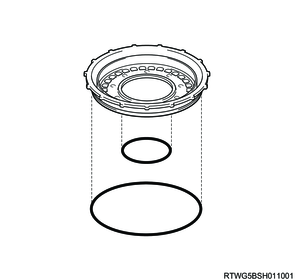
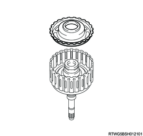
3) Coat the sliding surface of the No. 2 clutch drum sub-assembly with ATF.
4) Install the direct clutch piston to the No. 2 clutch drum sub-assembly.
Caution
- Be careful not to damage the O-rings and the No. 2 clutch drum sub-assembly and direct clutch piston.
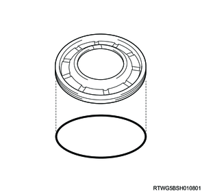
3. Direct clutch return spring sub-assembly installation
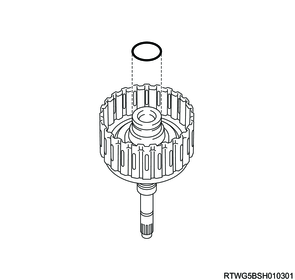
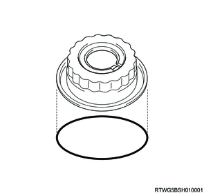
1) Coat a new O-ring with ATF.
Caution
- Do not reuse the O-ring.
2) Install it to clutch balancer No. 2.
| Inner diameter |
Thickness |
| 127.0 mm { 5.0000 in } |
2.62 mm { 0.1031 in } |
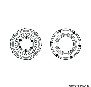
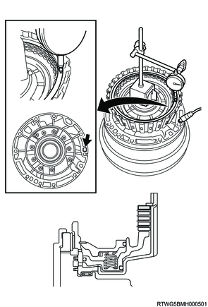
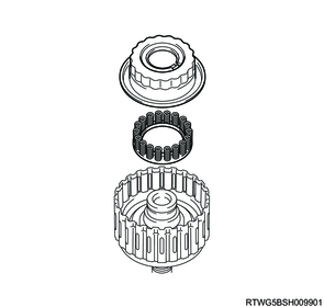
3) Install the direct clutch return spring and clutch balancer No. 2 to the No. 2 clutch drum sub-assembly.
Note
- Refer to the diagram, and install the direct clutch return spring by aligning it with the clutch balancer No. 2 arrow positions.
Caution
- Be careful not to damage the O-ring on clutch balancer No. 2.
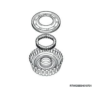
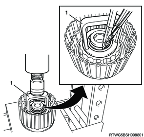
4) Place the special tool on clutch balancer No. 2, and compress the direct clutch return spring sub-assembly with a shop press.
Caution
- Be careful not to shorten the return spring too much.
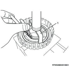
5) Using the special tool, install the snap ring in the groove.
Caution
- Be careful not to expand the snap ring too much.

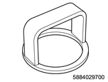
SST: 5-8840-2972-0 - spring compressor
Legend
- 5-8840-2972-0
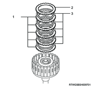
4. Clutch disc No.2 installation
1) Install the 5 plates, 5 discs and the flange to the No. 2 clutch drum sub-assembly as shown in the figure.
| Clutch |
Flange |
Disc |
Plate |
| C2 |
1 |
5 |
5 |
Caution
- Check the number and order of flange, discs and plates.
Note
- Install the plates, discs and the flange following the order shown in the figure.
- When measuring the No.2 clutch pack clearance, use a flange of 3.5 mm {0.1378 in} thickness.
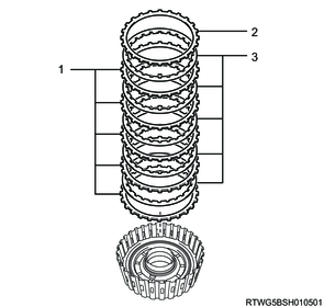
Legend
- Plate
- Flange
- Disc
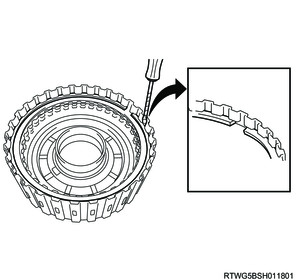
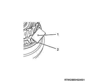
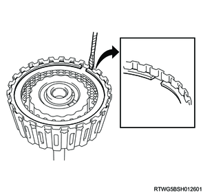
5. Clutch disc No.2 measurement
1) Using a screwdriver, install the snap ring in the groove.
Caution
- When installing the snap ring, set the end gap of the snap ring as shown in the figure.
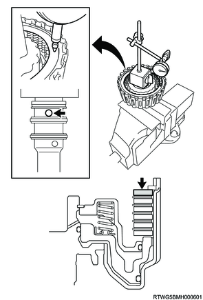
2) Place the oil pump assembly onto the torque converter assembly, and then place the No. 2 clutch drum sub-assembly onto the oil pump assembly.
Note
- As shown in the following diagram, prepare a board with a hole that matches the nozzle as necessary.
Legend
- Hole
- Board
3) Using a dial indicator, apply compressed air as shown in the figure.
196 kPa { 2 kgf/cm2 / 28 psi } Compressed air
Note
- When not replacing the disc and plate, use the installed flange.
- When using a new disc and plate, use a 3.5 mm {0.1378 in} flange.
Caution
- Measure the circumference of the flange at three places, and make sure that the average value is within the specified range.
- If the average value is outside the specified range, check the installation condition.
4) Measure the pack clearance, and adjust to align with the standard value.
Standard: 0.5 to 0.8 mm { 0.0197 to 0.0315 in } No. 2 clutch pack clearance
Caution
- If the No. 2 clutch pack clearance is not as specified, select an appropriate clutch flange No. 2.
| Flange thickness |
Thickness |
| 3.0 mm { 0.1181 in } |
|
| 3.1 mm { 0.1220 in } |
|
| 3.2 mm { 0.1260 in } |
|
| 3.3 mm { 0.1299 in } |
|
| 3.4 mm { 0.1339 in } |
|
| 3.5 mm { 0.1378 in } |
|
| 3.6 mm { 0.1417 in } |
|
| 3.7 mm { 0.1457 in } |
|
| 3.8 mm { 0.1496 in } |
6. Forward clutch piston installation
1) Coat a new O-ring with ATF.
Caution
- Do not reuse the O-ring.
2) Install it to the forward clutch drum sub-assembly.
| Inner diameter |
Thickness |
| 33.67 mm { 1.3256 in } |
2.62 mm { 0.1031 in } |
3) Coat a new O-ring with ATF.
Caution
- Do not reuse the O-ring.
4) Install it to the forward clutch piston.
| Inner diameter |
Thickness |
| 108.06 mm { 4.2543 in } |
3.1 mm { 0.1220 in } |
5) Install the forward clutch piston to the forward clutch drum sub-assembly.
Caution
- Be careful not to damage the O-rings on the forward clutch drum sub-assembly and forward clutch piston.
7. Forward clutch return spring sub-assembly installation
1) Coat a new O-ring with ATF.
Caution
- Do not reuse the O-ring.
2) Install it to clutch balancer No. 1.
| Inner diameter |
Thickness |
| 107.4 mm { 4.2283 in } |
2.62 mm { 0.1031 in } |
3) Install the forward clutch return spring sub-assembly and the clutch balancer No. 1 to the forward clutch drum sub-assembly.
Caution
- Be careful not to damage the O-rings on the clutch balancer No. 1.
4) Place the special tool on clutch balancer No. 1, and compress the forward clutch return spring sub-assembly with a shop press.
Caution
- Be careful not to shorten the return spring too much.
5) Using the special tool, install the snap ring in the groove.
Caution
- Be careful not to expand the snap ring too much.
SST: 5-8840-2970-0 - spring compressor
Legend
- 5-8840-2970-0
8. Clutch disc No.1 installation
1) Install the 5 plates, 5 discs and the flange to the forward clutch drum sub-assembly as shown in the figure.
| Clutch |
Flange |
Disc |
Plate |
| C1 |
1 |
5 |
5 |
Caution
- Check the number and order of flange, discs and plates.
Note
- Install the plates, discs and the flange following the order shown in the figure.
Legend
- Plate
- Flange
- Disc
9. Clutch disc No.1 measurement
1) Using a screwdriver, install the snap ring in the groove.
Caution
- When installing the snap ring, set the end gap of the snap ring as shown in the figure.
2) Using a dial indicator, apply compressed air as shown in the figure.
196 kPa { 2 kgf/cm2 / 28 psi } Compressed air
Note
- When not replacing the disc and plate, use the installed flange.
- When using a new disc and plate, use a 3.5 mm {0.1378 in} flange.
Caution
- Measure the circumference of the flange at three places, and make sure that the average value is within the specified range.
- If the average value is outside the specified range, check the installation condition.
3) Measure the pack clearance, and adjust to align with the standard value.
No. 1 clutch pack clearance
Standard: 0.75 to 1.05 mm { 0.0295 to 0.0413 in } No. 1 clutch pack clearance
Caution
- If the No. 1 clutch pack clearance is not as specified, select an appropriate clutch flange No. 1.
| Flange Thickness |
Thickness |
| 3.0 mm { 0.1181 in } |
|
| 3.1 mm { 0.1220 in } |
|
| 3.2 mm { 0.1260 in } |
|
| 3.3 mm { 0.1299 in } |
|
| 3.4 mm { 0.1339 in } |
|
| 3.5 mm { 0.1378 in } |
|
| 3.6 mm { 0.1417 in } |
|
| 3.7 mm { 0.1457 in } |
|
| 3.8 mm { 0.1496 in } |
|
| 3.9 mm { 0.1535 in } |
|
| 4.0 mm { 0.1575 in } |
|
| 4.1 mm { 0.1614 in } |
|
| 4.2 mm { 0.1654 in } |
10. Seal ring installation
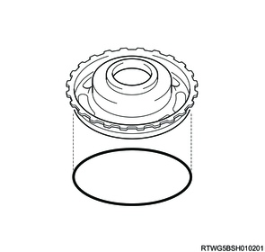
1) Coat the new 3 seal rings with ATF.
Caution
- Do not reuse the seal rings.
2) Install them to the forward clutch drum sub-assembly.
| Outer diameter |
Thickness |
| 31.97 mm { 1.2587 in } |
2.3 mm { 0.0906 in } |
Caution
- Be careful not to expand the seal rings too much.
- When shortening the seal rings, make sure to wrap them in the axial direction.
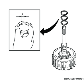
Standard value
a: 0 to 5 mm { 0.0000 to 0.1969 in }
3) Check that seal rings rotate smoothly after installing them.