1. ECM safety information
When replacing the ECM, the vehicle data must be written into the new ECM.
The scan tool used for the replacement procedure must be the same from start to finish. If the scan tool is changed midway, information cannot be written correctly.
Use the following procedure when replacing or programming the ECM.
| If communication could be established with the old ECM |
If communication could not be established with the old ECM |
|
| - |
ECM reset*1*2 |
ECM reset*1*2 |
| 1 |
Injector ID code upload |
- |
| 2 |
Vehicle speed correction data upload |
- |
| 3 |
ECM replacement |
ECM replacement |
| 4 |
VIN programming |
VIN programming |
| 5 |
Injector ID Code download |
Injector ID Code programming |
| 6 |
Vehicle speed correction data download |
Vehicle speed correction data programming |
| 7 |
Immobilizer function programming*2 |
Immobilizer function programming*2 |
| 8 |
Fuel Supply Pump Relearning |
Fuel Supply Pump Relearning |
| 9 |
ECU Lock |
ECU Lock |
| 10 |
DTC verification/clearing |
DTC verification/clearing |
Note
- *1: If reusing the ECM in another vehicle, perform the ECM reset in the original vehicle.
- *2: Perform only for models with immobilizer.
Caution
- Because "ECM reset" cannot be performed in a new vehicle, be sure to perform "ECM reset" in the original vehicle.
2. ECM reset
1. Precautions
Caution
- When installing the ECM to the vehicle, it must be security linked to the wireless access module using the programming procedure. Once this linking has been performed, the ECM cannot be installed to any other vehicle. Before transferring (switching) to the vehicle in which the complaint originated, the resetting procedure must be performed in the original vehicle and the security linkages between each module must be reset.
If the ECM to be replaced cannot establish communication with the scan tool, do not perform this operation.
2. Reset Engine Control Module
1) Connect the scan tool to the DLC.
2) Turn ON the ignition switch.
3) Select the scan tool item.
- Diagnostics > Body > WAM (Wireless Access Module) > Special Function > Engine Control Module > Reset Engine Control Module
4) Erase the immobilizer information of the ECM by following the on-screen instructions.
Caution
- Entering an incorrect security code causes a security wait time.
Note
- When turning the ignition switch ON and OFF by following the on-screen instructions, wait at least 5 seconds before turning it OFF or ON each time.
5) Turn OFF the ignition switch for 30 seconds.
6) Verify that the engine does not start with all the keys.
3. ECM upload
1. Precautions
If communication could not be established with the old ECM, do not perform the ECM data upload.
2. ECM data upload
1) Upload the following data from the old ECM to the scan tool.
- Injector ID Code
- Vehicle speed correction data
3. Injector ID code upload
1) Connect the scan tool to the DLC.
2) Turn ON the ignition switch.
3) Select the scan tool item.
- Diagnostics > Engine > RZ4E > Programming > Injector ID Code > Upload Injector ID
4) Follow the directions on the screen and upload the injector ID codes to a scan tool.
4. Vehicle speed correction data upload
1) Select the scan tool item.
- Diagnostics > Engine > RZ4E > Programming > Vehicle Speed Correction Data > Upload Vehicle Speed Correction Data
2) Upload the vehicle speed correction data to the scan tool by following the on-screen instructions.
3) After completing the upload, turn off the scan tool.
4) Turn OFF the ignition switch.
4. Preliminary and post procedures
1. Preliminary procedures
1) Open the engine hood.
2) Disconnect the battery cable from the battery negative terminal.
Caution
- After turning OFF the ignition switch (power mode for models with passive entry and start system), do not disconnect the battery cable within 3 minutes.
- If the battery cable is disconnected within 3 minutes, the vehicle electronic control system may malfunction.
- If the battery cable is disconnected, perform the setting of the front door power window switch with AUTO UP/AUTO DOWN function after connecting the battery negative terminal.
5. Glove box removal
1) Remove the glove box from the instrument panel.
RHD
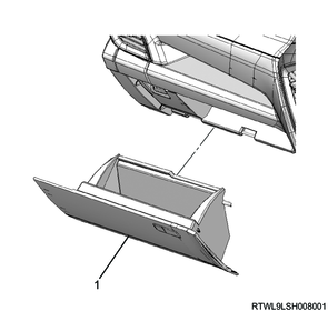
Legend
- Glove box
LHD
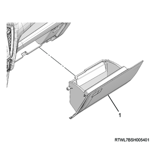
Legend
- Glove box
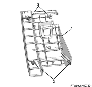
6. Instrument panel passenger-side lower cover removal
1) Remove the instrument panel passenger-side lower cover from the instrument panel.
RHD

Legend
- Instrument panel passenger-side lower cover
- Clip
LHD
Legend
- Instrument panel passenger-side lower cover
- Clip
2) Disconnect the connector from the instrument panel passenger-side lower cover.
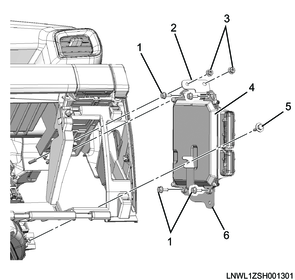
7. TCM removal
1) Remove the TCM and control module bracket as a set from the reinforcement.
2) Remove the TCM from the control module bracket.
RHD
Legend
- TCM
- Control module bracket
LHD
Legend
- TCM
- Control module bracket
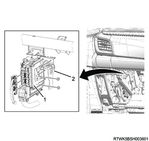
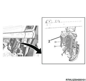
8. ECM removal
1) Remove the bracket and ECM as a set from the reinforcement.
2) Remove the ECM from the bracket.
RHD
Legend
- Bolt
- Bolt
- Nut
- Bracket
- Bracket
- ECM
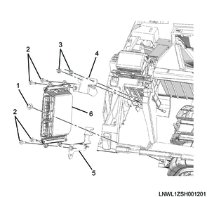
LHD
Legend
- Bolt
- Bracket
- Nut
- ECM
- Bolt
- Bracket