1. 1way clutch No.3 inspection
1) Hold 1 way clutch assembly No. 3 in place. Check that the rear planetary ring gear rotates when turned clockwise and does not rotate when turned counterclockwise.
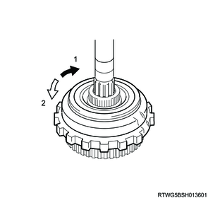
Legend
- Lock
- Free
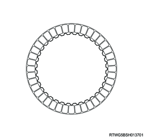
2. Brake disc No.1 inspection
1) Check the lining of all discs.
Note
- If the lining is flaking or has changed color, or if it is worn or the print mark is wearing away, replace with a new lining.
- When replacing, check the contact surfaces between the flange, plate and disc.
- If they are scratched or have changed color, replace with new parts.
- Before replacing with new discs, soak them at least 2 hours in ATF.
3. Brake disc No.2 inspection
1) Check the lining of all discs.
Note
- If the lining is flaking or has changed color, or if it is worn or the print mark is wearing away, replace with a new lining.
- When replacing, check the contact surfaces between the flange, plate and disc.
- If they are scratched or have changed color, replace with new parts.
- Before replacing with new discs, soak them at least 2 hours in ATF.
4. Brake disc No.4 inspection
1) Check the lining of all discs.
Note
- If the lining is flaking or has changed color, or if it is worn or the print mark is wearing away, replace with a new lining.
- When replacing, check the contact surfaces between the flange, plate and disc.
- If they are scratched or have changed color, replace with new parts.
- Before replacing with new discs, soak them at least 2 hours in ATF.

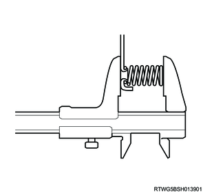
5. Brake piston return spring sub-assembly No.1 inspection
1) Using vernier calipers, measure the free length of brake piston return spring sub-assembly No. 1.
Caution
- If the free length is smaller than the minimum, replace brake piston return spring sub-assembly No. 1 with a new one.
Standard: 16.72 mm { 0.6583 in }
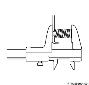
6. Brake piston return spring sub-assembly No.2 inspection
1) Using vernier calipers, measure the free length of the brake piston return spring sub-assembly No.2.
Caution
- If the free length is smaller than the minimum, replace brake piston return spring sub-assembly No. 2 with a new one.
Standard: 16.68 mm { 0.6567 in }
7. 1st and reverse brake return spring sub-assembly inspection
1) Using vernier calipers and a surface plate, measure the free length of the 1st and reverse brake return spring sub-assembly.
Caution
- If the free length is smaller than the minimum, replace the 1st and reverse brake return spring sub-assembly with a new one.
Standard: 11.44 mm { 0.4504 in }

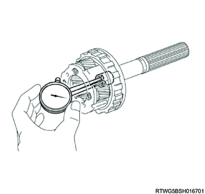
8. Front planetary gear assembly inspection
1) Using a feeler gauge, measure the front planetary gear pinion thrust clearance.
Caution
- If the clearance is not as specified, replace the front planetary gear assembly.
Standard: 0.2 to 0.6 mm { 0.01 to 0.02 in }

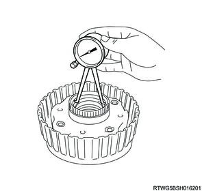
2) Using a caliper gauge, measure the inside diameter of the front planetary gear assembly bushing.
Caution
- Measure the inside diameter at several places (More than 3 places) and take an average. If the average is greater than the maximum, replace the front planetary gear assembly with a new one.
- When the front planetary gear assembly is replaced, inspect the surface in contact with the clutch hub sub-assembly. If the surface is scratched or discolored, replace the clutch hub sub-assembly with a new one.
Standard: 35.811 to 35.835 mm { 1.4099 to 1.4108 in }
9. Sun gear input drum inspection
1) Using a caliper gauge, measure the inside diameter of the sun gear input drum bushing.
Caution
- Measure the inside diameter at several places (More than 3 places) and take an average. If the average is greater than the maximum, replace the sun gear input drum with a new one.
- When the sun gear input drum is replaced, inspect the surface in contact with the clutch hub sub-assembly. If the surface is scratched or discolored, replace the clutch hub sub-assembly with a new one.
Standard: 35.811 to 35.835 mm { 1.4099 to 1.4108 in }

10. Middle planetary gear assembly inspection
1) Using a feeler gauge, measure the middle planetary gear pinion thrust clearance.
Caution
- If the clearance is not as specified, replace the middle planetary gear assembly.
Standard: 0.12 to 0.68 mm { 0.0047 to 0.0268 in }
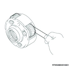
11. Rear planetary gear assembly inspection
1) Using a feeler gauge, measure the rear planetary gear pinion thrust clearance.
Caution
- If the clearance is not as specified, replace the rear planetary gear assembly.
Standard: 0.2 to 0.6 mm { 0.0079 to 0.0236 in }
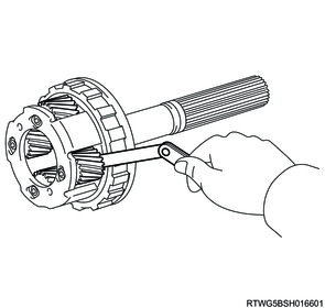
2) Using a caliper gauge, measure the inside diameter of the rear planetary gear bushing.
Caution
- Measure the inside diameter at several places (More than 3 places) and take an average. If the average is greater than the maximum, replace the rear planetary gear assembly with a new one.
- When the rear planetary gear assembly is replaced, inspect the surface in contact with the intermediate shaft. If the surface is scratched or discolored, replace the intermediate shaft with a new one.
Standard: 20.000 to 20.025 mm { 0.78740 to 0.78838 in }
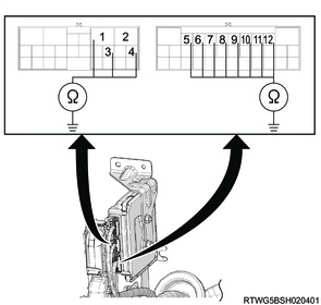
12. Engine harness inspection
1. Oil temperature sensor inspection
1) Disconnect the engine harness from the TCM.
2) Measure the resistance between the connector terminal combinations listed in the table using a DMM.
Note
- Check that resistances are as specified in the table.
Caution
- Do not damage the terminals.
| ATF temperature |
Resistance |
| -40 ℃ { -40 °F } |
161 kΩ MAX |
| -30 ℃ { -22 °F } |
36.3 to 52.1 kΩ |
| 10 ℃ { 50 °F } |
5.626 to 7.303 kΩ |
| 25 ℃ { 77 °F } |
3.5 kΩ |
| 110 ℃ { 230 °F } |
0.224 to 0.271 kΩ |
| 145 ℃ { 293 °F } |
0.102 to 0.121 kΩ |
| 150 ℃ { 302 °F } |
0.087 kΩ MIN |
Legend
- OT1+
- OT1-
- OT2-
- OT2+
3) Check for continuity between each connector terminal combinations listed in the table using a DMM.
Note
- Check that continuity is as specified in the table.
Caution
- Do not damage the terminals.
| Terminal name |
Continuity |
| OT1+ and Body earth |
No |
| OT1- and Body earth |
|
| OT2+ and Body earth |
|
| OT2- and Body earth |
Legend
- OT1+
- OT1-
- OT2-
- OT2+
2. Valve body assembly inspection
1) Disconnect the engine harness from the TCM.
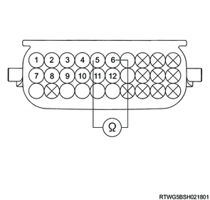
2) Measure the resistance between the connector terminal combinations listed in the table using a DMM.
Note
- Check that resistances are as specified in the table.
Caution
- Do not damage the terminals.
| Terminal name |
Resistance |
| SL and Body earth |
11 to 15 Ω |
| at 20 ℃ {68 °F} |
|
Legend
- SL
| Terminal name |
Resistance |
| SL1+ and SL1- |
5.0 to 5.6 Ω |
| SL2+ and SL2- |
|
| SL3+ and SL3- |
|
| SL4+ and SL4- |
|
| SLT+ and SLT- |
|
| SLU+ and SLU- |
|
| at 20 ℃ {68 °F} |
|
Legend
- SL4-
- SL3-
- SL4+
- SL3+
- SL2-
- SL2+
- SLT-
- SLT+
- SLU-
- SLU+
- SL-
- SL+
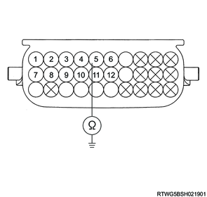
3) Check for continuity between each connector terminal combinations listed in the table using a DMM.
Note
- Check that continuity is as specified in the table.
Caution
- Do not damage the terminals.
| Terminal name |
Continuity |
| SL1+ and Body earth |
No |
| SL1- and Body earth |
|
| SL2+ and Body earth |
|
| SL2- and Body earth |
|
| SL3+ and Body earth |
|
| SL3- and Body earth |
|
| SL4+ and Body earth |
|
| SL4- and Body earth |
|
| SLT+ and Body earth |
|
| SLT- and Body earth |
|
| SLU+ and Body earth |
|
| SLU- and Body earth |
Legend
- SL4-
- SL3-
- SL4+
- SL3+
- SL2-
- SL2+
- SLT-
- SLT+
- SLU-
- SLU+
- SL1-
- SL1+
13. Transmission internal harness inspection
1. Oil temperature sensor inspection
1) Warm up ATF and insert the transmission fluid temperature sensor.
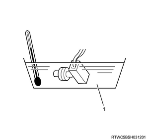
Legend
- ATF
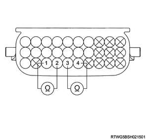
2) At each ATF temperature, measure the resistance between terminal OT1+ and OT1-, OT2+ and OT2- of the transmission internal harness connector using a DMM.
Note
- Check that the resistance is as specified in the table.
Caution
- Do not damage the terminals.
| ATF temperature |
Resistance |
| -40 ℃ { -40 °F } |
161 kΩ MAX |
| -30 ℃ { -22 °F } |
36.3 to 52.1 kΩ |
| 10 ℃ { 50 °F } |
5.626 - 7.303 kΩ |
| 25 ℃ { 77 °F } |
3.5 kΩ |
| 110 ℃ { 230 °F } |
0.224 - 0.271 kΩ |
| 145 ℃ { 293 °F } |
0.102 - 0.121 kΩ |
| 150 ℃ { 302 °F } |
0.087 kΩ MIN |
Legend
- OT1+
- OT1-
- OT2+
- OT2-
3) Check for continuity between each connector terminal combinations listed in the table using a DMM.
Note
- Check that continuity is as specified in the table.
Caution
- Do not damage the terminals.
| Terminal name |
Continuity |
| OT1+ and Body earth |
No |
| OT1- and Body earth |
|
| OT2+ and Body earth |
|
| OT2- and Body earth |
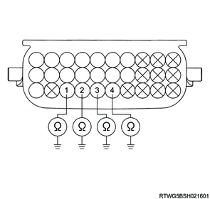
Legend
- OT1+
- OT1-
- OT2+
- OT2-
2. Valve body assembly inspection
1) Measure the resistance between the connector terminal combinations listed in the table using a DMM.
Note
- Check that resistances are as specified in the table.
Caution
- Do not damage the terminals.
| Terminal name |
Resistance |
| SL and Body earth |
11 to 15 Ω |
| at 20 ℃ {68 °F} |
|

Legend
- SL
| Terminal name |
Resistance |
| SL1+ and SL1- |
5.0 to 6.0 Ω |
| SL2+ and SL2- |
|
| SL3+ and SL3- |
|
| SL4+ and SL4- |
|
| SLT+ and SLT- |
|
| SLU+ and SLU- |
|
| at 20 ℃ {68 °F} |
|
Legend
- SLU+
- SLU-
- SL4+
- SL4-
- SL+
- SL-
- SL3+
- SL3-
- SLT+
- SLT-
- SL2+
- SL2-
2) Check for continuity between each connector terminal combinations listed in the table using a DMM.
Note
- Check that continuity is as specified in the table.
Caution
- Do not damage the terminals.
| Terminal name |
Continuity |
| SL1+ and Body earth |
No |
| SL1- and Body earth |
|
| SL2+ and Body earth |
|
| SL2- and Body earth |
|
| SL3+ and Body earth |
|
| SL3- and Body earth |
|
| SL4+ and Body earth |
|
| SL4- and Body earth |
|
| SLT+ and Body earth |
|
| SLT- and Body earth |
|
| SLU+ and Body earth |
|
| SLU- and Body earth |
Legend
- SLU+
- SLU-
- SL4+
- SL4-
- SL+
- SL-
- SL3+
- SL3-
- SLT+
- SLT-
- SL2+
- SL2-
14. Valve body assembly inspection
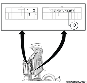
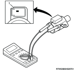
1. SL solenoid inspection
1) Measure the resistance between the SL solenoid terminal and SL solenoid body using a DMM.
Note
- Check that resistances are as specified in the table.
Caution
- Do not impact the SL solenoid.
- Do not remove the SL solenoid from the valve body assembly.
- Do not damage the terminals.
| Terminal name |
Resistance |
| SL solenoid terminal and SL solenoid body |
11 to 15 Ω |
| at 20 ℃ {68 °F} |
|
Legend
- Terminal
2) Inspect that the solenoid operates when the battery positive terminal is connected to the SL solenoid terminal and the battery negative terminal is connected to the solenoid body.
Caution
- Do not impact the SL solenoid.
- Do not damage the terminals.
3) Connect the battery positive terminal to the SL solenoid terminal and the battery negative terminal to the SL solenoid body, operate the solenoid, and inspect that the air flow is as shown in the diagram when air is applied.
Caution
- Do not impact the SL solenoid.
- Do not damage the terminals.
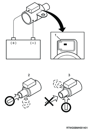
Legend
- Terminal
- ON
- OFF
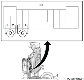
2. Clutch control solenoid (SL1, SL2, SL3, SL4) inspection
1) Measure the resistance between terminal 1 and terminal 2 of the clutch control solenoid (SL1, SL2, SL3, SL4) using a DMM.
Note
- Check that resistances are as specified in the table.
Caution
- Do not impact the clutch control solenoid.
- Do not damage the terminals.
- Do not remove clutch control solenoid (SL1, SL2, SL3, SL4) from the valve body assembly.
| Terminal name |
Resistance |
| Terminal 1 and Terminal 2 |
5.0 to 5.6 Ω |
| at 20 ℃ {68 °F} |
|
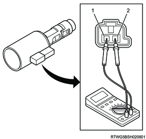
Legend
- -
- +
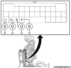
2) Inspect that clutch control solenoid (SL1, SL2, SL3, SL4) operates when the battery positive terminal is connected to clutch control solenoid (SL1, SL2, SL3, SL4) positive terminal via the bulb (12-21W) and the battery negative terminal is connected to the negative terminal.
Caution
- Do not apply impact to the clutch control solenoid (SL1, SL2, SL3, SL4).
- Do not damage the terminals.

Legend
- -
- +
- Bulb (12 to 21 W)
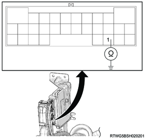
3. Line pressure control solenoid (SLT) inspection
1) Measure the resistance between terminal 1 and terminal 2 of the line pressure control solenoid (SLT) using a DMM.
Note
- Check that resistances are as specified in the table.
Caution
- Do not impact the line pressure control solenoid (SLT).
- Do not damage the terminals.
- Do not remove the line pressure control solenoid (SLT) from the valve body assembly.
| Terminal name |
Resistance |
| Terminal 1 and Terminal 2 |
5.0 to 5.6 Ω |
| at 20 ℃ {68 °F} |
|
Legend
- -
- +
2) Inspect that the solenoid operates when the battery positive terminal is connected to the line pressure control solenoid (SLT) positive terminal via the bulb (12-21W) and the battery negative terminal is connected to the negative terminal.
Caution
- Do not impact the line pressure control solenoid (SLT).
- Do not damage the terminals.
Legend
- -
- +
- Bulb (12 to 21 W)
4. Lock-up control solenoid (SLU) inspection
1) Measure the resistance between terminal 1 and terminal 2 of the Lock-up control solenoid (SLU) using a DMM.
Note
- Check that resistances are as specified in the table.
Caution
- Do not impact the lock-up control solenoid (SLU).
- Do not damage the terminals.
- Do not remove the lock-up control solenoid (SLU) from the valve body assembly.
| Terminal name |
Resistance |
| Terminal 1 and Terminal 2 |
5.0 to 5.6 Ω |
| at 20 ℃ {68 °F} |
|
Legend
- -
- +
2) Inspect that the solenoid operates when the battery positive terminal is connected to the lock-up control solenoid (SLU) positive terminal via the bulb (12-21W) and the battery negative terminal is connected to the negative terminal.
Caution
- Do not impact the lock-up control solenoid (SLU).
- Do not damage the terminals.
Legend
- -
- +
- Bulb (12 to 21 W)