1. Component views
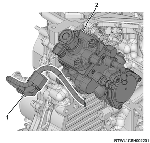
Fuel supply pump
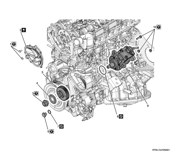
Part name
- Nut and bolt
- Timing chain lower cover
- Supply pump gear nut
- Supply pump sprocket
- Supply pump gear
- Plug
- Gasket
- O-ring
- Fuel supply pump
- Nut and bolt
Tightening torque
1: 10 N・m { 1.0 kgf・m / 89 lb・in }
3: 130 N・m { 13.3 kgf・m / 96 lb・ft }
6: 50 N・m { 5.1 kgf・m / 37 lb・ft }
10: 25 N・m { 2.5 kgf・m / 18 lb・ft }
2. Radiator removal
3. Exhaust pipe removal
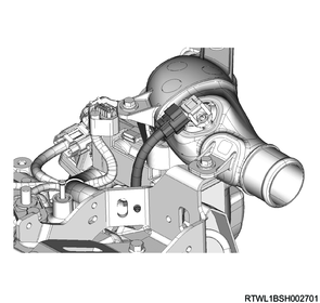
4. DPD removal
1) Remove the heat protector from the turbocharger.

Legend
- Heat protector
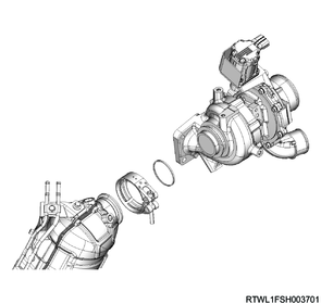
2) Remove the V-band from the DPD.
3) Remove the DPD and gasket from the turbocharger.
4) Disconnect the differential pressure hose from the DPD.

Legend
- White paint
- Green paint
5) Remove the DPD front upper bracket from the turbocharger upper bracket and DPD.
6) Remove the DPD front lower bracket from the turbocharger lower bracket and DPD.
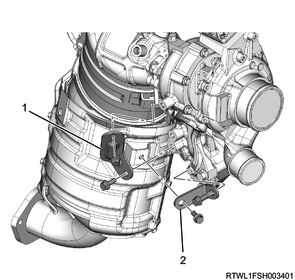
Legend
- DPD front upper bracket
- DPD front lower bracket
7) Remove the DPD rear bracket from the oil cooler side bracket and DPD.
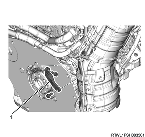
Legend
- DPD rear bracket
8) Remove the exhaust pipe bracket from the crankcase.
Note
- If removing the DPD from the vehicle, remove after removing the turbocharger.

5. Air duct removal
1) Remove the PCV hose from the cylinder head cover and air duct.
Legend
- PCV hose
- Clamp
2) Remove the air duct from the air cleaner and turbocharger.
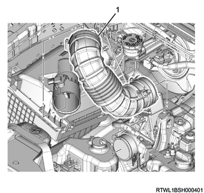
Legend
- Air duct
6. Battery removal
1) Disconnect the battery ground cable from the frame.
2) Disconnect the battery cable from the battery.
3) Remove the battery bracket from the frame.
4) Remove the battery from vehicle.
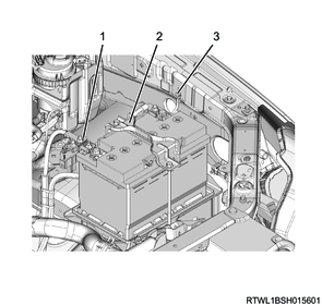
Legend
- Battery cable
- Battery bracket
- Battery ground cable
7. Air cleaner removal
1) Disconnect the connector from the MAF and IAT sensor.
2) Remove the air cleaner from the vehicle.
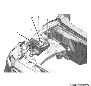
Legend
- Air cleaner
- MAF and IAT sensor
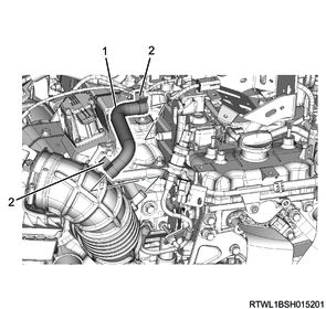
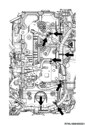
8. EGR cooler water hose disconnect
1) Disconnect the EGR cooler water feed hose from the EGR cooler.
2) Disconnect the EGR cooler water return hose from the EGR cooler.

Legend
- EGR cooler water return hose
- EGR cooler water feed hose
9. EGR cooler removal
1) Remove the upper heat protector from the EGR duct.
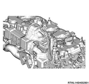
2) Remove the lower heat protector from the EGR duct.
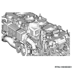
3) Remove the harness bracket from the EGR duct.
4) Remove the EGR cooler and gasket from the cylinder head and exhaust manifold.
Caution
- Do not reuse the gasket.
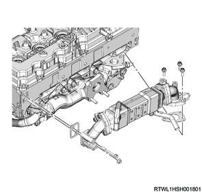
5) Remove the EGR duct and gasket from the EGR cooler.
Caution
- Do not reuse the gasket.

Legend
- EGR duct
- EGR cooler
- EGR duct
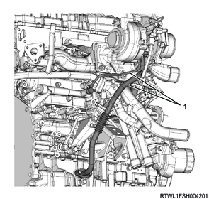
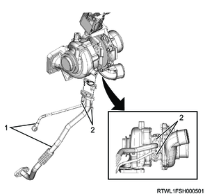
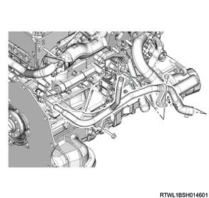
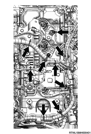
10. Turbocharger water hose disconnect
1) Disconnect the turbocharger water feed hose from the water feed and return pipe.
2) Disconnect the turbocharger water return hose from the water feed and return pipe.

Legend
- Turbocharger water feed hose
- Turbocharger water return hose
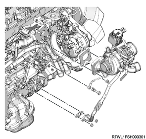
11. Turbocharger oil pipe disconnect
1) Disconnect the turbocharger oil pipe from the oil cooler and crankcase.
Caution
- To prevent the intrusion of foreign material, seal the connections.
- Do not reuse the gasket.
Legend
- Turbocharger oil pipe
12. Turbocharger bracket removal
1) Remove the turbocharger bracket from the cylinder block.

Legend
- Turbocharger bracket
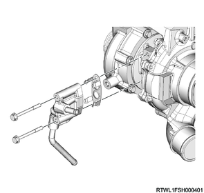
13. Turbocharger removal
1) Disconnect the connector from the turbocharger.
2) Remove the following parts as a set from the exhaust manifold.
- Turbocharger
- Turbocharger oil pipe
- Water feed and return pipe
Caution
- To prevent the intrusion of foreign material, seal the connections.
- Do not reuse the gasket.
3) Remove the turbocharger oil pipe and gasket from the turbocharger.
Caution
- To prevent the intrusion of foreign material, seal the connections.
- Do not reuse the gasket.
Legend
- Turbocharger oil pipe
- Bolt
4) Remove the water feed and return pipe, as well as the gasket from the turbocharger.
Caution
- Do not reuse the gasket.
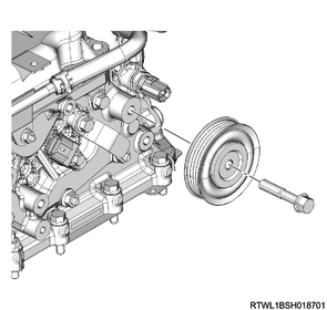
14. A/C compressor drive belt removal
1. M/T models (Euro 5 or above)
1) Loosen the tension pulley lock nut.
2) Loosen the tension pulley adjust bolt.
3) Remove the A/C compressor drive belt from the following parts.
- Tension pulley
- A/C compressor
- Crankshaft pulley
- Idle pulley
Legend
- Lock nut
- Adjust bolt
- Idle pulley
- A/C compressor drive belt
- Idle pulley
2. Except M/T models (Euro 5 or above)
1) Loosen the tension pulley lock nut.
2) Loosen the tension pulley adjust bolt.
3) Remove the A/C compressor drive belt from the following parts.
- Tension pulley
- A/C compressor
- Crankshaft pulley
Legend
- Lock nut
- Adjust bolt
- A/C compressor drive belt
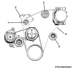
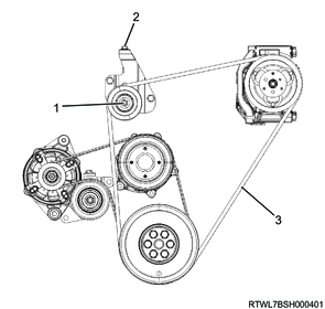
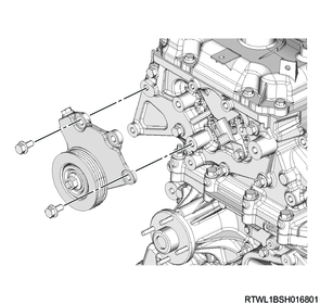
15. Cooling fan belt removal
1) Loosen the tension pulley lock nut.
2) Loosen the tension pulley adjust bolt.
3) Remove the cooling fan belt from the following parts.
- Fan pulley
- Generator
- Crankshaft pulley
MT models

Legend
- Adjust bolt
- Cooling fan belt
- Lock nut
AT models
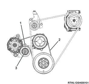
Legend
- Adjust bolt
- Cooling fan belt
- Lock nut
16. Generator removal
1) Disconnect the B-terminal from the generator.
2) Disconnect the connector from the generator.
3) Remove the upper bracket from the generator and timing gear case.
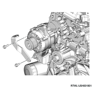
4) Remove the generator from the lower bracket.

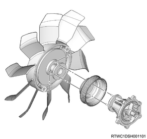
17. Cooling fan removal
1) Remove the cooling fan and cooling fan clutch as a set from the water pump.
2) Remove the fan pulley from the water pump.
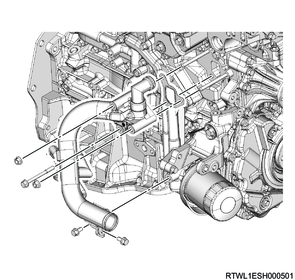
18. Water intake pipe removal
1) Remove the water intake pipe and water hose as a set from the oil filter and oil cooler.
Caution
- Do not reuse the gasket.
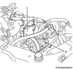
19. Oil filter element removal
1) Remove the oil filter element from the oil filter bracket using the special tool.
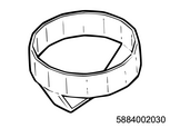
SST: 5-8840-0203-0 - oil filter wrench
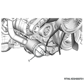
Legend
- 5-8840-0203-0
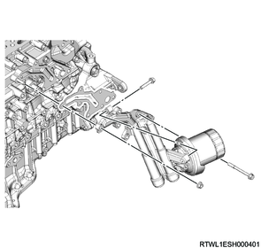
20. Oil filter removal
1) Remove the oil filter and gasket from the oil cooler.
Caution
- Do not reuse the gasket.
21. EGR water pipe removal
1) Disconnect the water hose from the water intake pipe and return hose.
2) Install the EGR water pipe to the oil cooler and turbocharger lower bracket.
22. A/C compressor disconnect
1) Disconnect the A/C compressor from the A/C compressor bracket.
Legend
- A/C compressor bracket
- A/C compressor
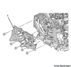
23. A/C compressor bracket removal
1) Remove the A/C compressor bracket from the cylinder head.
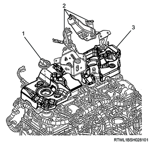
24. EGR cooler bypass control solenoid valve removal
1) Disconnect the connector from the EGR cooler bypass control solenoid valve.
2) Disconnect the vacuum hose from the EGR cooler bypass control solenoid valve.
3) Remove the EGR cooler bypass control solenoid valve and bracket as a set from the inlet manifold.

Legend
- EGR cooler bypass control solenoid valve
25. Fuel hose disconnect
1) Disconnect the fuel feed hose from the fuel supply pump.
2) Disconnect the fuel return hose from the fuel leak-off pipe.

Legend
- Fuel feed hose
- Fuel return hose
26. Fuel feed pipe removal
1) Remove the fuel feed pipe from the fuel supply pump and common rail (fuel rail).
Caution
- Do not reuse the fuel feed pipe.
- Cover the exposed section to prevent the intrusion of foreign material.

Legend
- Fuel supply pump
- Fuel feed pipe
- Common rail (fuel rail)
27. Fuel leak-off pipe removal
1) Remove the fuel leak-off pipe from the fuel supply pump and common rail (fuel rail).
Caution
- Cover the exposed section to prevent the intrusion of foreign material.

Legend
- Leak-off hose
- Fuel leak-off pipe
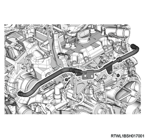
28. Water pipe removal
1) Remove the water pipe from the following parts.
- Thermostat
- Cylinder head
- Turbocharger
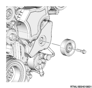
29. Tension pulley removal
1) Remove the tension pulley from the cylinder head.
30. Starter motor removal
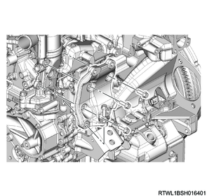
31. Exhaust differential pressure sensor removal
32. Differential pressure sensor bracket removal
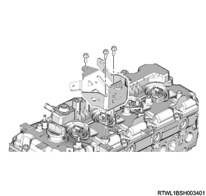
1) Disconnect the following sensor harnesses from the harness bracket.
- Exhaust gas temperature sensor 1 (Front of DPD filter)
- Exhaust gas temperature sensor 2 (Front of oxidation catalyst)
- Heated oxygen sensor
2) Remove the differential pressure sensor bracket from the cylinder head cover.
3) Remove the harness bracket from the cylinder head cover.
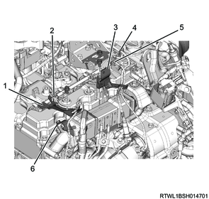
Legend
- Harness bracket
- Exhaust gas temperature sensor 1 (Front of DPD filter)
- Differential pressure sensor bracket
- Heated oxygen sensor
- Exhaust gas temperature sensor 2 (Front of oxidation catalyst)
- Harness bracket
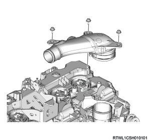
33. Intake air duct removal
1) Disconnect the connector from the boost pressure sensor.
2) Remove the intake air duct from the intake throttle valve.
34. Air duct bracket removal
1) Remove the air duct bracket from the cylinder head cover.
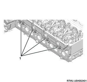
35. Fuel leak-off hose removal
1) Disconnect the connector from the injector.
2) Remove the fuel leak-off hose from the leak-off pipe.
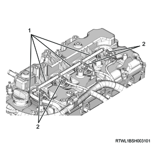
Legend
- Fuel leak-off hose
- Injector connector
3) Remove the injector leak-off pipe from the injector.
Caution
- Do not reuse the injector leak-off pipe or clip.
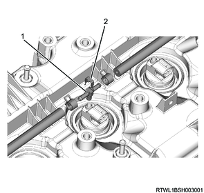
Legend
- Injector leak-off pipe
- Clip
36. Intake throttle valve removal
1) Disconnect the connector from the intake throttle valve.
2) Remove the following parts from the inlet manifold.
- Air duct bracket
- Intake throttle valve
- Gasket
Caution
- Do not reuse the gasket.
Legend
- Air duct bracket
- Intake throttle valve
- Gasket
37. Glow plug removal
1) Disconnect the connector from the glow plug.
Legend
- Connector
2) Remove the glow plug from the cylinder head.

Legend
- Glow plug
38. Cylinder head cover removal
1) Disconnect the PCV hose from the cylinder head cover.
2) Disconnect the harness clip from the cylinder head cover.
RHD
LHD
3) Remove the harness bracket from the cylinder head cover.
Note
- For models with urethane covers, remove together with the urethane cover.
- When removing the urethane cover, remove the oil filler cap before performing work.
Models with urethane covers
Legend
- Filler cap
- Harness bracket
- Urethane cover
4) Remove the cylinder head cover from the cylinder head.
Caution
- Do not reuse the gasket.
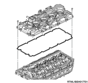
5) Remove the oil seal from the lower side of the cylinder head cover.
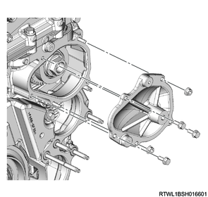
39. Timing chain upper cover removal
1) Remove the idle pulley from the timing chain upper cover.
2) Disconnect the connector from the CMP sensor.

Legend
- CMP sensor
3) Remove the timing chain upper cover from the cylinder head.
Legend
- Timing chain upper cover
40. Timing chain lower cover removal
1) Remove the idle pulley from the timing chain lower cover.
2) Remove the noise cover from the timing chain lower cover.
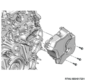
3) Remove the timing chain lower cover from the gear case cover.
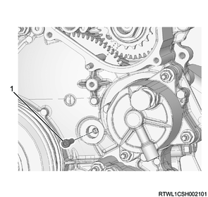
41. Timing chain removal
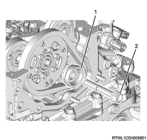
1) Turn the crankshaft in the forward direction (clockwise) to align idle gear A side installation or removal position mark with the supply pump gear side installation or removal position mark.
Note
- Referring to the diagram, align the supply pump installation or removal position mark.
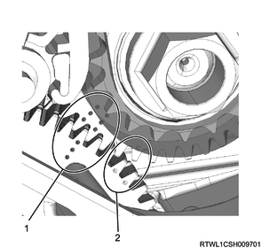
Legend
- Supply pump installation or removal position mark
- TDC position mark
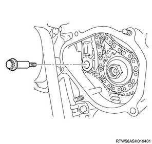
2) Remove the plug from the gear case cover.
Caution
- Do not reuse the gasket.
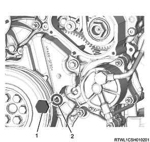
Legend
- Plug
- Gasket
3) Secure the scissors gear of idle gear A using an M6 lock bolt.
Caution
- Do not rotate the crankshaft with the lock bolt installed.
Legend
- M6 lock bolt
4) Install the special tool to the starter installation section of the rear plate.
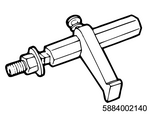
SST: 5-8840-0214-0 - crankshaft stopper
5) Remove the oil feed pipe from the timing chain tensioner.
Caution
- Do not reuse the gasket.
6) Remove the timing chain tensioner and gasket from the cylinder head.
Caution
- Do not reuse the gasket.
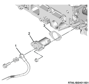
Legend
- Oil feed pipe
- Timing chain tensioner
- Gasket
7) Remove the oil feed pipe from the cylinder block.
Caution
- Do not reuse the gasket.
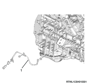
Legend
- Oil feed pipe
8) Remove the timing chain lever pivot from the timing chain tension lever.
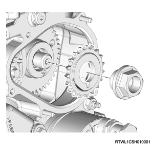
9) Remove the idle gear D center bolt and sleeve from the idle gear D shaft.
Legend
- Sleeve
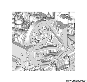
- Idle gear D center bolt
10) Remove the idle gear D sprocket and timing chain as a set from idle gear D and the supply pump gear sprocket.
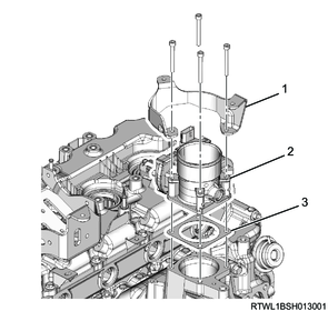
42. Fuel supply pump removal
1) Remove the supply pump sprocket from the supply pump gear.
2) Remove the supply pump gear from the fuel supply pump using a gear puller.

3) Disconnect the connector from the fuel supply pump.
Legend
- Fuel supply pump connector
- Fuel supply pump
4) Remove the fuel supply pump from the timing gear case.
5) Remove the O-ring from the fuel supply pump.
Caution
- Do not reuse the O-ring.
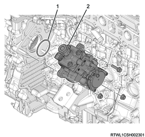
Legend
- O-ring
- Fuel supply pump