1. Component views
Front disc brake
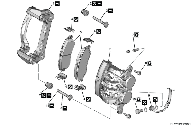
Part name
- Brake support
- Boot
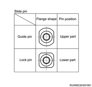
- Slide pin (Lock pin and guide pin)
- Pad clip
- Brake pad (With shim)
- Brake caliper
- Breeder bolt
- Lock bolt
- Brake hose
- Bolt
- Pin bushing
Tightening torque
7: 9 to 13 N・m { 0.9 to 1.3 kgf・m / 80 to 115 lb・in }
8: 32 to 42 N・m { 3.3 to 4.3 kgf・m / 24 to 31 lb・ft }
10: 29 to 39 N・m { 3.0 to 4.0 kgf・m / 21 to 29 lb・ft }
2. Disc brake pad installation
1) Referring to the diagram, install the pad clip to the brake support.
Caution
- Do not mix-up the top and bottom or right and left of the pad clip.
- Do not reuse the pad clips.
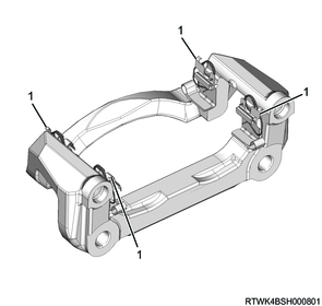
Legend
- Pad clip
2) Referring to the diagram, apply grease to the rubber coated shim.
Note
- Apply grease to both sides of the shim.
Caution
- Grease should not ooze from the shim.
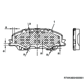
Legend
- Grease application area
Standard value
a: 5 mm { 0.20 in }
3) Install the rubber coated shim and stainless steel shim to the disc brake pad.
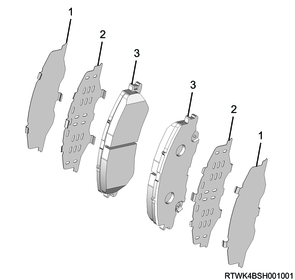
Legend
- Stainless steel shim
- Rubber coated shim
- disc brake pad
4) Check that the grease does not ooze from the shim.
Note
- Wipe off if grease oozes from the shim.
5) Referring to the diagram, install the disc brake pad and shim to the brake support.
Note
- Insert the brake pad into the gap indicated by the arrow so that the tip of the spring is caught in the notch of the brake pad.
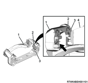
Legend
- Brake support
- Spring
- Pad clip
- disc brake pad
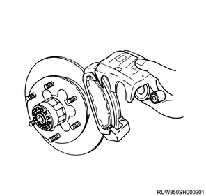
6) Lower the brake caliper to the original position.
Note
- Because the spring of the pad clip separates the disc brake pad from the disc, press the disc brake pad against the disc to install.
Caution
- Do not damage the brake hose by twisting or pulling it.
Caution
- Make sure that the dust boot does not shoot out from the piston end.
- Be careful not to get the dust boot caught between the piston and the pad.
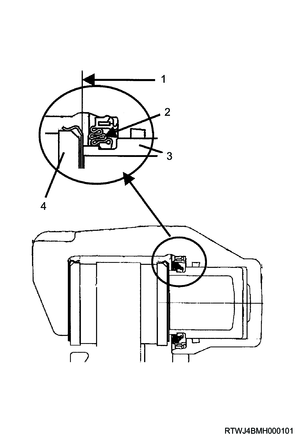
Legend
- Piston end surface
- Dust boot
- Piston
- Pad

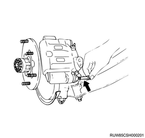
7) Install the lock pin side lock bolt to the brake caliper.
Tightening torque: 32 to 42 N・m { 3.3 to 4.3 kgf・m / 24 to 31 lb・ft }
8) Connect the brake hose center bracket to the knuckle or shock absorber.
Tightening torque: 14 to 25 N・m { 1.4 to 2.5 kgf・m / 10.3 to 18.4 lb・ft }
2WD (High ride suspension specifications), 4WD
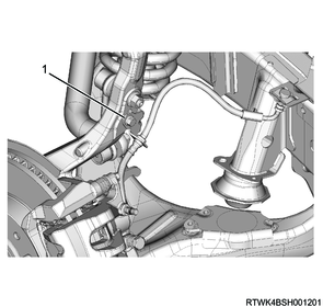
Legend
- Center bracket
2WD (Except high ride suspension specifications)
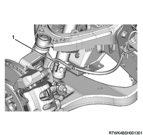
Legend
- Center bracket
3. Disc wheel installation
1. Models with aluminum wheels
1) Temporarily tighten the disc wheel to the vehicle.
2) Lower vehicle.
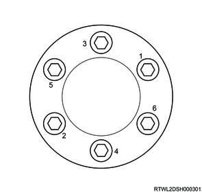
3) Final tighten the wheel nut in the order shown in the diagram.
Tightening torque: 120 N⋅m {12 kgf⋅m / 87 lb⋅ft}
Caution
- After completing installation, make sure to further tighten the wheel nuts to the specified torque after the vehicle has been driven a distance exceeding the standard value.
Standard: 50 to 100 km { 31 to 62 mile }
4) Install the wheel cap to the disc wheel.
Note
- For models with 18-inch aluminum wheels, align the wheel cap groove with the air valve before installing.
5) Check that the surfaces of the wheel cap and wheel are flat.
Note
- If the surfaces are not flat, the wheel cap may fall off.
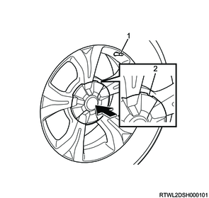
Legend
- Valve
- Wheel cap groove
2. Models with steel wheels
1) Temporarily tighten the disc wheel and wheel cap to the vehicle.
2) Lower vehicle.
3) Final tighten the wheel nut in the order shown in the diagram.
Tightening torque: 120 N⋅m {12 kgf⋅m / 87 lb⋅ft}
Caution
- After completing installation, make sure to further tighten the wheel nuts to the specified torque after the vehicle has been driven a distance exceeding the standard value.
Standard: 50 to 100 km { 31 to 62 mile }