1. Component views
Common rail (fuel rail)
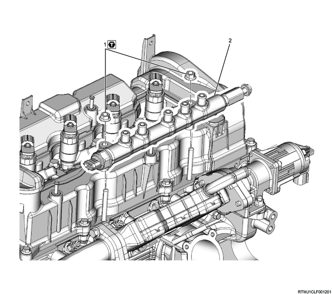
Part name
- Nut
- Common rail (fuel rail)
Tightening torque
1: 25 N・m { 2.5 kgf・m / 18 lb・ft }
2. Common rail (fuel rail) installation
1) Install the common rail (fuel rail) to the cylinder head.
Tightening torque: 25 N・m { 2.5 kgf・m / 18 lb・ft }
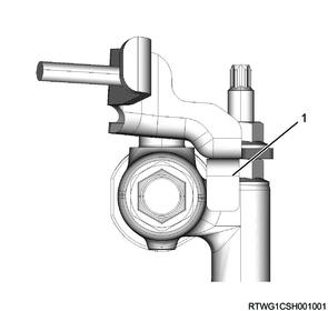
Caution
- Do not hold the FRP sensor.
- Take care not to damage the connector section of the FRP sensor.

2) Install the connector to the FRP sensor.
3) Install the bracket to the cylinder head.
Note
- Install so that the detent makes contact with the common rail (fuel rail).
Tightening torque: 25 N・m { 2.5 kgf・m / 18 lb・ft }
Legend
- Detent
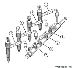
3. Injection pipe installation
1) Temporarily tighten the injection pipes to the injectors and common rail (fuel rail) in the order shown in the diagram.
Caution
- Do not reuse the injection pipe.
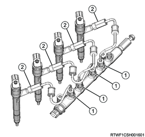
2) Final tighten the injection pipes to the injectors and common rail (fuel rail) in the order shown in the diagram.
Tightening torque: 35 N・m { 3.6 kgf・m / 26 lb・ft }
4. Fuel feed pipe installation
1) Install the fuel feed pipe to the fuel supply pump and common rail (fuel rail).
Caution
- Do not reuse the fuel feed pipe.
Tightening torque: 35 N・m { 3.6 kgf・m / 26 lb・ft }

Legend
- Fuel feed pipe
2) Install the clip to the fuel feed pipe.
Tightening torque: 10.0 N・m { 1.0 kgf・m / 89 lb・in }
5. Fuel leak-off pipe installation
1) Install the fuel leak-off pipe to the common rail (fuel rail) and flywheel housing.
Tightening torque: 20.2 N・m { 2.1 kgf・m / 15 lb・ft } Common rail (fuel rail) side
Tightening torque: 25 N・m { 2.5 kgf・m / 18 lb・ft } Flywheel housing side

Legend
- Fuel leak-off pipe
2) Connect the fuel leak-off hose to the fuel leak-off pipe.
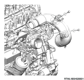
6. Intake air duct installation
1) Install the intake duct to the intake throttle valve.
Tightening torque: 10.0 N・m { 1.0 kgf・m / 89 lb・in } Bolt
Tightening torque: 4.0 N・m { 0.4 kgf・m / 35 lb・in } Clamp (Intake throttle side)
Clamp installation direction
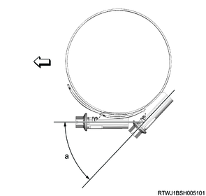
Standard value
a: 45 °
2) Connect the connector to the boost pressure and CAC temperature sensor.
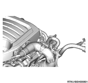
7. Air intake hose installation
1) Install the air intake hose to the intake air duct and intercooler.
Caution
- Align the marks on the pipe side and hose side.
Tightening torque: 5.0 N・m { 0.5 kgf・m / 44 lb・in }
Legend
- Intercooler
- Air intake hose
- Intake air duct
- Clamp
8. Engine cover installation
1) Install the engine cover to the engine.
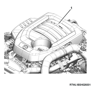
Legend
- Engine cover
9. Preliminary and post procedures
1. Post procedures
1) Connect the battery cable to the battery negative terminal.
2) Referring to the following, perform the setting of the front door power window switch with AUTO UP/AUTO DOWN function.
Refer to "9.Body, Cab, Accessories 9T.Glass, Windows, Mirrors front door power window switch setting".
3) Close the engine hood.