1. Component views
Rear differential cage (φ220 mm {8.66 in}) (Differential lock)
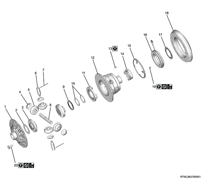
Part name
- Differential cage A
- Thrust washer
- Side gear
- Pinion washer
- Pinion gear
- Pinion shaft S
- Lock pin
- Pinion shaft L
- Return spring
- Thrust washer
- Cam ring
- Differential cage B
- Screw bolt
- Plunger
- Position plate
- Coil assembly
- Solenoid washer
- Ring gear
- Bolt
- Bolt
Tightening torque
13: 4.5 N・m { 0.5 kgf・m / 40 lb・in }
19: 6.9 N・m { 0.7 kgf・m / 61 lb・in }
20: 145 N・m { 14.8 kgf・m / 107 lb・ft }
2. Final drive disassembly
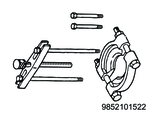
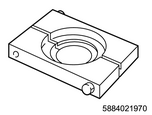
1) Secure the final drive to a work bench using the special tool.
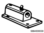
SST: 5-8840-0003-0 - base
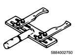
SST: 5-8840-0275-0 - holding fixture
Legend
- 5-8840-0003-0
- 5-8840-0275-0
2) Place alignment marks on the bearing cap and differential carrier.
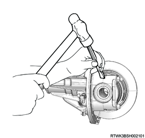
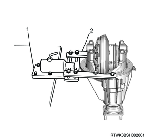
3) Disconnect the coil assembly connector.
Note
- Unlock by breaking the claw section shown in the diagram using a flathead screwdriver, etc.
Legend
- Intermediate connector
- Claw section
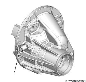
4) Remove the bearing cap from the differential carrier.
5) Remove the differential cage from the differential carrier.
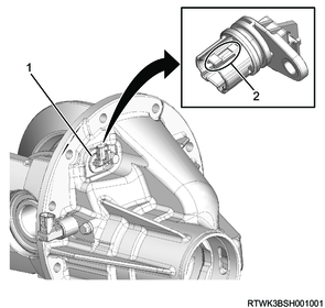
6) Remove the bolt, and then remove the intermediate connector.
Caution
- Do not reuse the intermediate connector.
Legend
- Intermediate connector
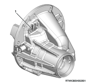
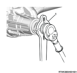
7) Remove the bolt, and then remove the differential lock position switch.
Caution
- Do not remove the differential lock position switch before removing the differential cage.
This is because the differential lock position switch may be broken.
Legend
- Differential lock position switch
8) Remove the side bearing outer race from the differential cage.
Caution
- Organize the removed side bearings according to left/right installation positions and bearing race combinations by using labels, etc.
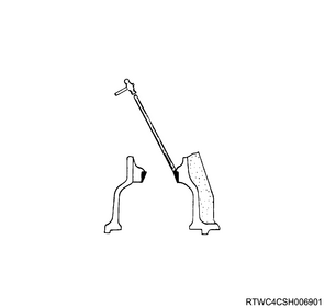
9) Remove the side bearing inner race from the differential cage using the special tool.
Caution
- Do not reuse the side bearing inner race.
SST: 9-8521-0152-2 - bearing remover
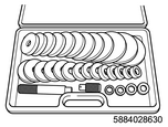
SST: 5-8840-2863-0 - driver tool set
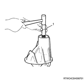
10) Pry up the staked portion of the flange nut.
11) Remove the flange from the drive pinion using the special tool.
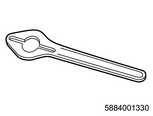
SST: 5-8840-0133-0(J-8614-11) - flange holder
Legend
- 5-8840-0133-0
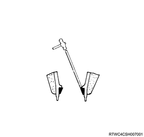
12) Remove the drive pinion from the differential carrier using a brass rod and hammer.
Legend
- Brass rod
13) Remove the collapsible distance piece from the drive pinion.
14) Remove the inner bearing inner race from the drive pinion using the special tool.
SST: 5-8840-2197-0 - separator
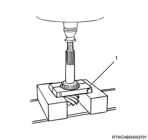
Legend
- 5-8840-2197-0
15) Remove the adjust shim from the drive pinion.
Caution
- Organize the removed adjust shims according to thickness and number using labels, etc.
16) Remove the oil seal from the differential carrier.
17) Remove the outer bearing inner race from the differential carrier.
18) Remove the outer bearing outer race from the differential carrier using a brass rod and hammer.
Note
- Apply a brass rod, etc., to the differential carrier inner notch, and tap out with a hammer to remove.
19) Remove the inner bearing outer race from the differential carrier using a brass rod and hammer.
20) Apply a brass rod, etc., to the differential carrier inner notch, and tap out with a hammer to remove.
3. Differential cage disassembly
1) Measure the backlash of the side gear and pinion gear.
Standard: 0.10 to 0.20 mm { 0.004 to 0.008 in }
2) Remove the ring gear from the differential cage.
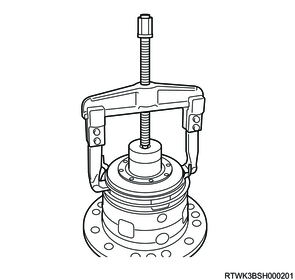
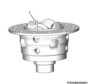
3) Remove the coil assembly and solenoid washer using a puller.
Caution
- Be sure to check that the position plate is free (it can be pushed by hand) before installing the pulley.
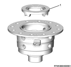
4) Remove the plunger from the differential cage.
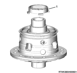
Legend
- Plunger
5) Remove the position plate from the differential cage.
Caution
- Do not reuse the bolt.
This is because locking agent is applied to the threaded portion.
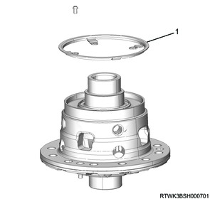
Legend
- Position plate
6) Place alignment marks on differential cage B and differential cage A.
7) Remove differential cage A from differential cage B.
8) Remove the side gear and thrust washer from differential cage B.
9) Remove the lock pin from differential cage B.
Note
- Pull up the lock pin with your fingers to remove it.
Legend
- Lock pin
10) Remove the following parts from differential cage B.
- Pinion washer
- Pinion gear
- Pinion shaft
11) Remove the return spring and thrust washer from the cam ring.
12) Remove the cam ring from differential cage B.
Legend
- Cam ring