1. Valve guide inspection
1. Visual inspection
1) Inspect the valve stem and valve guide inner diameter section for the following.
- Scratches
- Abnormal wear
Note
- Replace the valve and valve guide as a set if a malfunction is found.
2. Valve guide measurement
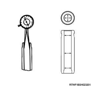
1) Measure the valve guide inner diameter using a dial gauge.
Standard: 5.500 to 5.515 mm { 0.2165 to 0.2171 in }
Limit: 5.565 mm { 0.2191 in }
Note
- Replace the valve and valve guide as a set if a malfunction is found.
2. Valve inspection
1. Valve stem measurement
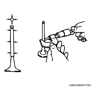
1) Measure the diameter of the valve stem using a micrometer.
Standard: 5.465 to 5.480 mm { 0.2152 to 0.2157 in } Inlet valve
Limit: 5.455 mm { 0.2148 in } Inlet valve
Standard: 5.459 to 5.474 mm { 0.2149 to 0.2155 in } Exhaust valve
Limit: 5.449 mm { 0.2145 in } Exhaust valve
Note
- Replace the valve and valve guide as a set if the measured value is less than the limit.
2. Clearance measurement between valve guide and valve stem
1) Measure the clearance from the difference between the valve guide inner diameter and the valve stem outer diameter.
Standard: 0.020 to 0.050 mm { 0.0008 to 0.0020 in } Inlet valve
Limit: 0.110 mm { 0.0043 in } Inlet valve
Standard: 0.026 to 0.056 mm { 0.0010 to 0.0022 in } Exhaust valve
Limit: 0.116 mm { 0.0046 in }
Note
- Replace the valve and valve guide as a set if the measured value exceeds the limit.
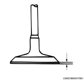
3. Valve thickness measurement
1) Measure the thickness of the valve.
Standard: 1.0 mm { 0.0394 in } Inlet valve
Limit: 0.8 mm { 0.031 in } Inlet valve
Standard: 1.0 mm { 0.0394 in } Exhaust valve
Limit: 0.8 mm { 0.031 in } Exhaust valve
Note
- Replace the valve and valve guide as a set if the measured value is less than the limit.
4. Valve protrusion amount measurement
1) Remove the carbon and water deposit on the bottom surface of the cylinder head.
2) Install the valve to the cylinder head.
3) Measure the valve protrusion amount from the cylinder head lower surface at the location where it is the largest.
Standard: 0.7 mm { 0.0276 in }
Limit: 0.2 mm { 0.0079 in }
Note
- Replace the valve seat or cylinder head if the measured value is less than the limit.

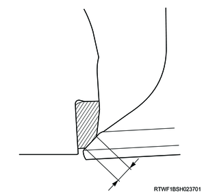
5. Valve seat contact width measurement
1) Measure the touching width of the valve seat.
Standard: 1.50 mm { 0.059 in } Inlet valve
Limit: 2.37 mm { 0.0933 in } Inlet valve
Standard: 1.50 mm { 0.0591 in } Exhaust valve
Limit: 2.37 mm { 0.0933 in } Exhaust valve
Note
- If the contact surface is damaged or rough, repair the valve seat.
- Replace the valve, valve guide, and valve seat as a set, or replace the valve and cylinder head if the measured value exceeds the limit.
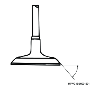
6. Valve contact surface measurement
1) Measure the valve contact surface.
Standard: 45 °
Note
- Replace the valve if the measured value is not the standard value.
3. Valve spring inspection
1. Visual inspection
1) Inspect the valve spring for the following.
- Damage
- Abnormal wear
Note
- If an abnormal condition is found, replace the valve spring.
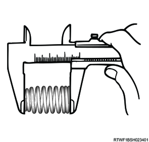
2. Valve spring free length measurement
1) Measure the free length of the valve spring using a vernier caliper.
Note
- Replace the valve spring if the measured value is not the standard value.
Standard: 51.14 mm { 2.0134 in } Inlet spring (Without paint)
Standard: 56.66 mm { 2.2307 in } Exhaust spring (With paint)
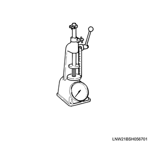
3. Valve spring installation load measurement
1) Install the valve spring to load test equipment.
Standard: 26.0 mm { 1.024 in } Inlet spring height
Standard: 25.5 mm { 1.004 in } Exhaust spring height
Note
- Replace the valve spring if the measured value is less than the limit.
Standard: 330.4 N { 33.7 kg / 74 lb } Inlet spring
Limit: 298.2 N { 30.4 kg / 67 lb } Inlet spring
Standard: 402.0 N { 41.0 kg / 90 lb } Exhaust spring
Limit: 362.8 N { 37.0 kg / 82 lb } Exhaust spring
4. Valve seat insert inspection
1. Cleaning
1) Remove the carbon from the valve seat insert surface.
2. Visual inspection
1) Inspect the valve seat insert for the following.
- Scratches
- Uneven sections
Note
- If there are scratches or uneven sections, adjust the valve seat insert.
3. Valve seat insert adjustment
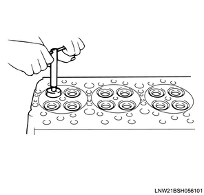
1) Adjust the valve seat to the standard value using a seat cutter.
Note
- Minimize scratches and other uneven sections to adjust the contact width to the specified value.
Caution
- Get rid of only the scratches and uneven portions, but be careful not to over-cut.
- Use an adjustable valve cutter pilot.
- The valve cutter pilot should not be allowed to scrape inside the valve guide.
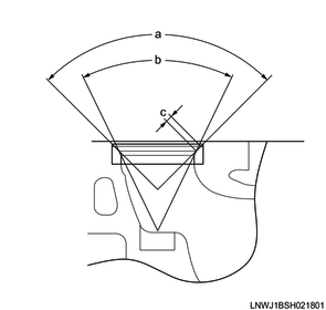
Standard value
a: 90 ° Angle 1, inlet valve
a: 90 ° Angle 1, exhaust valve
b: 48 ° Angle 2, inlet valve
b: 60 ° Angle 2, exhaust valve
c: 1.5 mm { 0.059 in } Contact width
2) Apply the compound to the valve seat surface.
3) Fit the valve by turning and lightly tapping.
Caution
- Confirm that there is even contact around the entire circumference.
- After fitting, completely remove the compound.

5. Cylinder head inspection
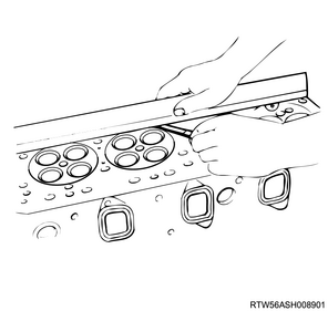
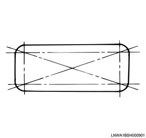
1) Measure the deformation of the cylinder block installation surface using a simple straight ruler and feeler gauge.
Note
- Referring to the diagram, measure the 4 sides and across opposite corners.
- If the measured value exceeds the limit, replace the cylinder head.
Caution
- Do not polish the cylinder head lower surface.
Limit: 0.075 mm { 0.0030 in }
2) Measure the deformation of the exhaust manifold installation surface using a simple straight ruler and feeler gauge.
Note
- Measure the 4 sides and across opposite corners.
Limit: 0.20 mm { 0.0079 in }
0.40 mm { 0.0157 in } Repair limit
Note
- If the measured value exceeds the repair limit, replace the cylinder head.

6. Valve stem end cap inspection
1. Visual inspection
1) Inspect the valve stem end cap for the following.
- Scratches
- Abnormal wear
Note
- Replace the valve stem end cap if an abnormal condition is found.
7. Rocker arm inspection
1. Visual inspection
1) Inspect the rocker arm for the following.
- Wear
- Damage
- Stuck roller
- Rattly roller
Note
- Replace the rocker arm if a malfunction is found.
8. HLA inspection
1. Visual inspection
1) Inspect the HLA for the following.
- Scratches
- Abnormal wear
Note
- Replace the HLA if an abnormal condition is found.
2. Air inclusion inspection
1) Push the HLA plunger with your fingers and inspect for sinking.
Note
- If there is a sponge-like feeling and sinking, bleed air in the HLA.
Caution
- Do not push the plunger with strong force for a long period of time.
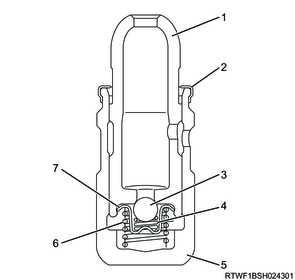
Legend
- Plunger
- Stop ring
- Check ball
- Check spring
- Body
- Return spring
- Retainer
3. Bleed the air.
1) Put the HLA into the container vertically.
2) Add clean engine oil until the HLA end is submerged in it.
3) Using a 1 mm {0.04 in} diameter bar, push the plunger with your fingers and move it up and down while pushing the check ball.
Caution
- Do not push the check ball with a strong force.
4) Check that the air stops coming out of the plunger.
5) Perform the air inclusion inspection, and check that there is no sponge-like feeling when depressing with your fingers.
Note
- If sinking persists after repeating several times, replace the HLA.
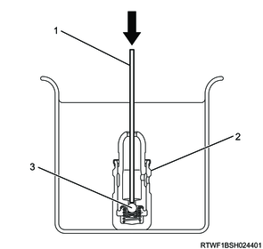
Legend
- 1 mm {0.04 in} diameter rod
- HLA
- Check ball