1. Lighting systems
1. Headlight system
This circuit comprises the headlights, ignition switch, lighting switch and passing switch on the combination switch, and BCM. When the lighting switch is turned ON in the headlight position, the headlight relay or BCM will be activated and the headlights will be illuminated. When the headlights are illuminated, the optical axis of the headlight can be faced upward and downward alternately using the lighting switch. The passing switch is not related to the position of the headlight switch. The optical axis will face upward only when the switch lever is being pulled up.
2. Clearance light system
This circuit comprises the clearance lights, ignition switch, lighting switch on the combination switch, and BCM. When the lighting switch is turned ON in the headlight or taillight position, the taillight relay or BCM will be activated and the clearance lights will be illuminated.
3. Automatic headlight system
This circuit comprises the headlights, ignition switch, lighting switch on the combination switch, rain and light sensor, and BCM. When the lighting switch is turned to AUTO position, the BCM turns ON or OFF each light according to the brightness detected by the rain and light sensor.
Note
- Refer to the BCM chapter for the details on the automatic headlight system.

Legend
- Combination switch
- Rain and light sensor
- Headlight
4. Fog light system
This circuit comprises the fog lights, ignition switch, lighting switch and fog light switch on the combination switch, and relays. When the lighting switch is turned ON in the headlight or taillight position, the taillight relay or BCM will be activated. When the fog light switch is turned ON while keeping this state, the fog light relay will be activated and the fog lights will be illuminated.
5. Rear fog light system
This circuit comprises the rear fog lights, ignition switch, lighting switch and rear fog light switch on the combination switch, and relays. When the lighting switch is turned ON in the headlight or taillight position, the taillight relay or BCM will be activated. When the rear fog light switch is turned ON while keeping this state, the rear fog light relay will be activated and the rear fog lights will be illuminated.
6. Turn signal light and hazard light system
This circuit comprises the turn signal lights, ignition switch, turn signal switch on the combination switch, hazard warning switch, and flasher unit or BCM. When the turn signal switch or hazard warning flasher switch is turned ON, the flasher unit or BCM will be activated and the turn signal lights will be illuminated. The turn signal lights are illuminated by the answer-back function of the keyless entry system, etc.
Note
- Refer to the BCM chapter for the details on the turn signal light and hazard light system.
Legend
- Combination switch
- Hazard warning flasher switch
7. Dome light system
This circuit comprises the dome light, door switches, BCM, etc. The BCM illuminates the dome light when the door switch is turned ON.

Legend
- Door switch
- Dome light
8. Taillight and stoplight system
This circuit comprises the taillights, stoplights, ignition switch, lighting switch on the combination switch, stoplight switch, and BCM. When the lighting switch is turned ON in the headlight or taillight position, the taillight relay or BCM will be activated and the taillights will be illuminated. The stoplights illuminate according to the operation of the stoplight switch.
Legend
- Stoplight switch
9. License plate light system
This circuit comprises the license plate lights, ignition switch, lighting switch on the combination switch, and BCM. When the lighting switch is turned ON in the headlight or taillight position, the taillight relay or BCM will be activated and the license plate lights will be illuminated.
10. Illumination light system
This circuit comprises the illumination lights, ignition switch, lighting switch on the combination switch, and BCM. When the lighting switch is turned ON in the headlight or taillight position, the taillight relay or BCM will be activated and the illumination lights will be illuminated.
11. Backup light system
M/T models
This circuit comprises the backup lights and the backup light switch. When the backup light switch installed to the transmission is turned ON, the backup lights will illuminate.
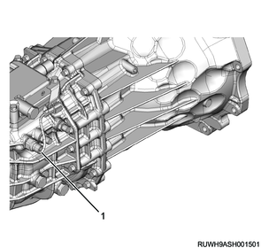
Legend
- Backup light switch
A/T models
This circuit comprises the backup light and inhibitor switch. When the inhibitor switch installed to the transmission is turned ON, the backup light illuminates.
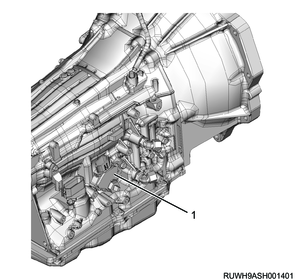
Legend
- Backup light switch
12. Bulb location diagram
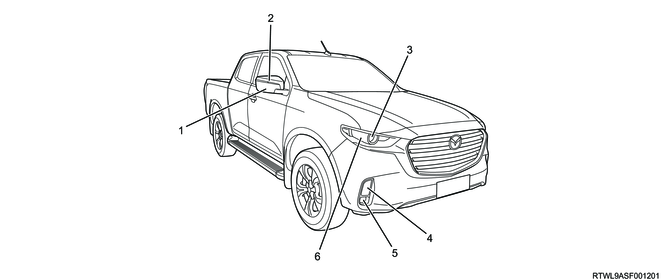
Low grade type
Legend
- Outside rearview mirror
- Turn signal light (outside rearview mirror mounted type)
- Headlight
- Turn signal light/clearance light
- Front fog light
- Daytime running light (DRL)
- Turn signal light (front fender mounted type)
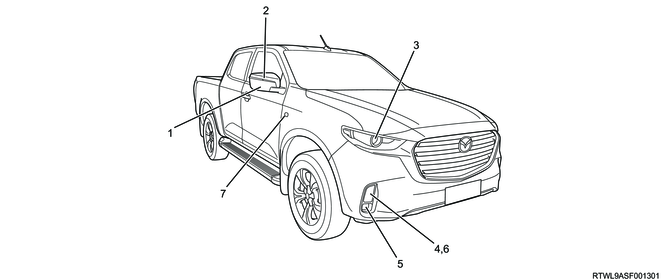
High grade type
Legend
- Outside rearview mirror
- Turn signal light (outside rearview mirror mounted type)
- Headlight
- Turn signal light/clearance light
- Fog light
- Daytime running light (DRL)
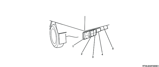
Except models with horizontal type taillights
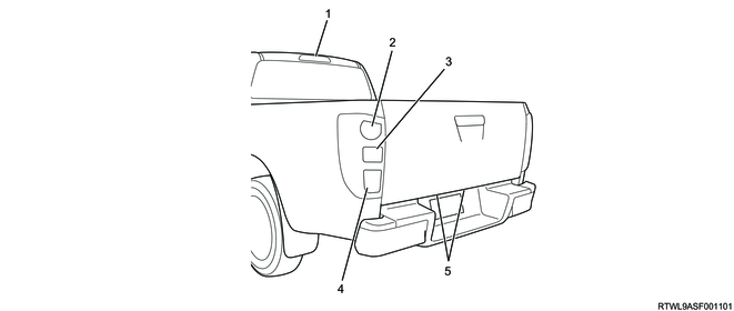
Legend
- High mounted stoplight
- Taillight and stoplight
- Rear turn signal light
- Backup light
- License plate light
Models with horizontal type taillights
Legend
- Taillight and stoplight
- Rear turn signal light
- Backup light
- Rear fog light (Driver side)
- License plate light
2. Wiper, washer systems
1. Windshield wiper and washer system
The wiper and washer system comprise the following units. The system is activated when the vehicle is running or the ignition switch is in the ON position.
- Wiper, washer switch
- BCM
- Wiper motor
- Washer motor
- Washer nozzle
- Washer tank
- Wiper arm and blade
- Rain and light sensor
The BCM controls the wiper low/high speed drive, the wiper intermittent or automatic drive, and the windshield washer linked drive of the wiper motor. The BCM detects that each wiper switch and the windshield washer switch are ON.
Note
- For models without BCM, the motor directly detects that the switch is ON.
1) Windshield washer
When the windshield washer switch is turned ON, the washer motor will operate. Slightly later the BCM drives the wiper motor at a low speed.
2) Wiper intermittent drive
When the wiper switch is at the INT position, the BCM drives the wiper motor intermittently at low speed.
3) Wiper automatic drive
When the wiper switch is at the AUTO position, the BCM drives the wiper motor at proper speed according to the rainfall detected by the rain and light sensor and the vehicle driving speed.
Note
- Refer to the BCM chapter for the details on the wiper automatic drive.
4) Wiper low-speed drive
When the wiper switch is at the LO position, the BCM drives the wiper motor at low speed.
5) Wiper high-speed drive
When the wiper switch is at the HI position, the BCM drives the wiper motor at high speed.
3. Electrical control, entertainment
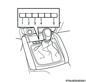
1. Layout of switches
RHD
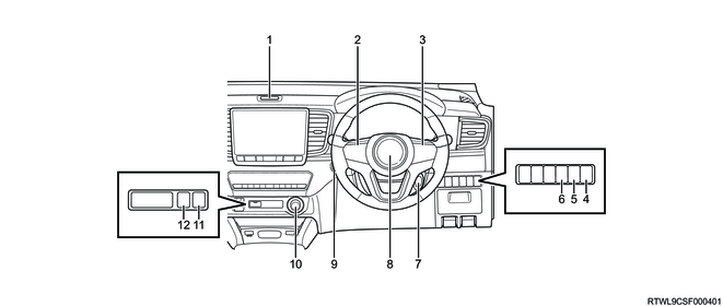
Legend
- Hazard warning flasher switch
- Steering wheel remote control (LH)
- Steering wheel remote control (RH)
- Illumination control switch
- Headlight leveling switch
- ESC OFF switch
- Starter switch (models without passive entry and start system)
- Horn button
- Engine start/stop button (models with passive entry and start system)
- 4WD switch
- Hill descent control switch
- Rear differential lock switch
LHD
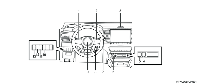
Legend
- Steering wheel remote control (LH)
- Steering wheel remote control (RH)
- Hazard warning flasher switch
- Rear differential lock switch
- Hill descent control switch
- 4WD switch
- Engine start/stop button (models with passive entry and start system)
- Starter switch (models without passive entry and start system)
- Horn button
- TPMS load selector switch
- ESC OFF switch
- Headlight leveling switch
- Illumination control switch
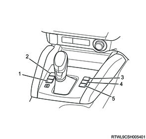
M/T models (RHD)
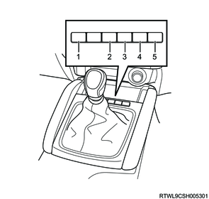
Legend
- Heated seat switch (Left front seat)
- Parking aid system OFF switch
- Hill descent control switch
- Rear differential lock switch
- Heated seat switch (right front seat)
M/T models (LHD)
Legend
- Heated seat switch (Left front seat)
- Rear differential lock switch
- Hill descent control switch
- Parking aid system OFF switch
- Heated seat switch (right front seat)
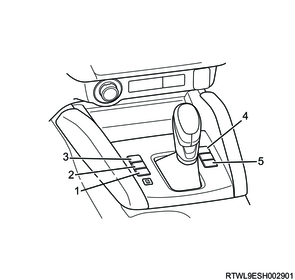
A/T models (RHD)
Legend
- Heated seat switch (Left front seat)
- Parking aid system OFF switch
- Hill descent control switch
- Rear differential lock switch
- Heated seat switch (right front seat)
A/T models (LHD)
Legend
- Heated seat switch (Left front seat)
- Rear differential lock switch
- Hill descent control switch
- Parking aid system OFF switch
- Heated seat switch (right front seat)
4. Instrumentation, driver info.
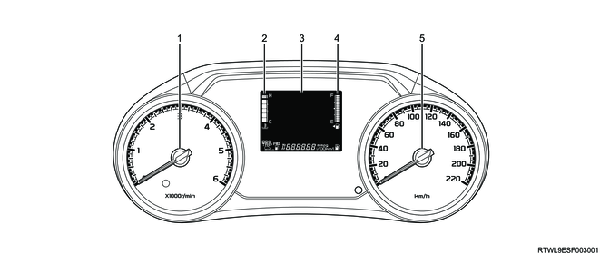
1. Instrument panel cluster system
The following meters, gauges, warning lights, and indicator lights are assembled to the instrument panel cluster.
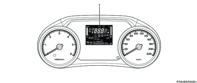
Models with MID

Legend
- Tachometer
- Engine coolant temperature gauge
- Multi-information display (MID)
- Fuel gauge
- Speedometer
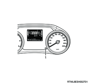
Models with LCD
Legend
- Tachometer
- Engine coolant temperature gauge
- Liquid crystal display (LCD)
- Fuel gauge
- Speedometer
These components cannot be replaced separately because they are integrated with the instrument panel cluster.
They communicate with control units such as the ECM, the TCM, the BCM, and the EHCU via CAN.
1) Speedometer
The speedometer indicates based on the signal output from the ECM. The ECM corrects the vehicle speed signal from the EHCU and sends it to the instrument panel cluster via CAN communication.
2) Tachometer
The tachometer indicates the engine speed based on the engine speed signal output from the ECM. The ECM detects the signal from the CKP sensor, and the engine speed signal is input to the instrument panel cluster via CAN communication.
3) Fuel gauge
The fuel gauge displays the remaining fuel level based on the signal output from the fuel tank unit. The fuel gauge displays the remaining fuel level as low when the resistance detected by the fuel tank unit is high.
The fuel gauge displays the remaining fuel level as high when the resistance detected by the fuel tank unit is low.
4) Engine coolant temperature gauge
The engine coolant temperature gauge displays the engine coolant temperature based on the engine coolant temperature signal output from the ECM. The ECM detects the engine coolant temperature signal from the engine coolant temperature sensor, and the signal is input to the engine coolant temperature gauge via CAN communication.
2. Warning light, indicator light
Models with MID
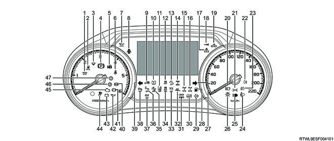
Legend
- Glow plug indicator light
- Fuel filter warning light
- Water separator warning light
- Parking brake warning light
- Anti-theft system indicator light
- Front seat belt warning light (driver seat)
- Engine oil level warning light
- Door open warning light
- TPMS loading indicator light
- TPMS warning light
- LDW OFF indicator light
- ESC OFF indicator light
- Hill descent control indicator light
- 4WD indicator light
- Rear differential lock indicator light (Green)
- Rear differential lock failure warning light (Yellow)
- Master warning light
- Key monitor warning light
- SVS indicator light
- Automatic high beam indicator light
- Light position indicator light
- Rear fog light indicator light
- Front fog light indicator light
- Headlight automatic leveling warning light
- High beam indicator light
- LED headlight warning light
- Turn signal indicator light – right
- Low fuel warning light
- DPD operator regeneration indicator light
- Steering system failure warning light
- CHECK 4WD warning light
- 4WD low indicator light
- TCS OFF indicator light
- ESC OFF indicator light
- AEB OFF indicator light
- BSM OFF indicator light
- ELK OFF indicator light
- Parking aid system OFF indicator light
- Turn signal indicator light – left
- ABS warning light
- Brake system warning light
- Engine oil pressure warning light
- Generator warning light
- SRS airbag warning light
- Malfunction indicator light (MIL)
- Automatic transmission fluid temperature warning light
- Check trans warning light
Models with LCD
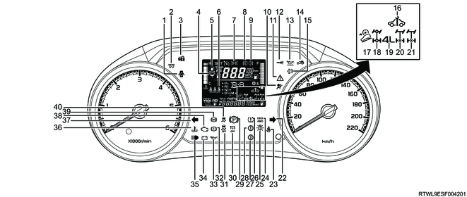
Legend
- Door open warning light
- Glow plug indicator light
- Anti-theft system indicator light
- Water separator warning light
- Fuel filter warning light
- Second seat belt warning light
- Light position indicator light
- Front fog light indicator light
- Rear fog light indicator light
- SRS airbag warning light
- Master warning light
- Key monitor warning light
- Engine oil level warning light
- TPMS loading indicator light
- DPD operator regeneration indicator light
- SVS indicator light
- Hill descent control indicator light
- 4WD indicator light
- 4WD low indicator light
- Rear differential lock indicator light (Green)
- Rear differential lock failure warning light (Yellow)
- Turn signal indicator light – right
- Front seat belt warning light
- CHECK 4WD warning light
- LED headlight warning light
- TPMS warning light
- Automatic transmission fluid temperature warning light
- Check trans warning light
- Parking brake warning light
- TCS OFF indicator light
- ESC OFF indicator light
- Brake system warning light
- Engine oil pressure warning light
- Generator warning light
- High beam indicator light
- Engine overheat warning light
- Turn signal indicator light – left
- Check engine warning light/Malfunction indicator light
- ABS warning light
- ESC warning light
Models with radar sensors
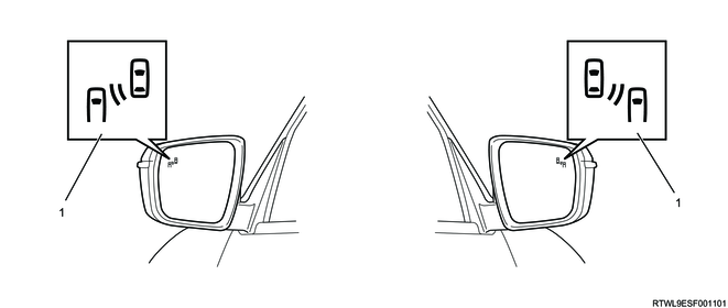
Legend
- BSM indicator light
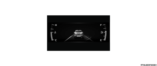
3. Multi-information display (MID)
The multi-information display has the ability to display the following information. The trip knob operation enables the display switching and other operations.
Legend
- Multi-information display
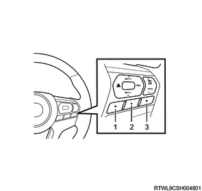
Legend
- MID mode L switch
- MID mode confirm switch
- MID mode R switch

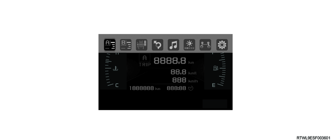
Legend
- Display area 1
- Display area 2
- Display area 3
- Display area 4
1) Full display
- Warning-related information
- Operation-related information
- Setting screen
2) Display area 1
- Clock
- Calendar
- Warning light
- Outside temperature
- Vehicle speed
- Range
- Odometer
- Navigation bar
3) Display area 2
- Warning-related information
- Operation-related information
- Audio-related information
- Navigation-related information
4) Display area 3
- Engine coolant temperature gauge
- Fuel gauge
5) Display area 4
- Operation-related information
4. Navigation bar
When the MID mode R/L switch is pressed, the navigation bar is displayed on the multi-information display. The following can be selected on the navigation bar.
- Trip meter A and operation-related information display
- Trip meter B and operation-related information display
- Eco graph display
- Audio system linked display*1
- Driving support system information display
- Illumi level display*2
- Vehicle drive status display
- Settings display
*1 Displayed only for 9 inch display equipped models.
*2 Displayed only when Manual is selected in the illumination mode.
Navigation bar
1) Operation-Related Information Display (Trip Meter A/B)
The average fuel efficiency, instantaneous fuel efficiency, elapsed time, and average vehicle speed can be switched to display for TRIP A or TRIP B. If the odometer/trip meter indication is TRIP A, each data of interval A is displayed, and if it is TRIP B, each data of interval B is displayed. Each displayed data can be reset by pressing and holding the MID mode confirm switch.

Legend
- Trip meter
- Average fuel efficiency
- Average vehicle speed
- Elapsed time
- Odometer
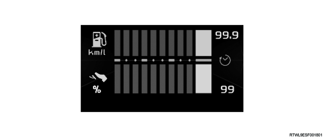
2) Eco graph display
The accelerator opening position and instantaneous fuel efficiency can be displayed.
3) Audio system linked display
The information from the audio system can be displayed.
4) Driving support system information display
Information on the preceding vehicle and lane detected by the stereo camera can be displayed.
Adaptive Cruise Control (ACC)
When the preceding vehicle is detected, the inter-vehicular distance with the preceding vehicle is displayed in 3 levels.

Legend
- Preceding vehicle indicator
- Inter-vehicular distance display
Lane Departure Warning (LDW), Lane Departure Prevention (LDP), Lane Keep Assist System (LKAS)
Information on the recognized lanes is displayed. Also, the operational status of each system is displayed.
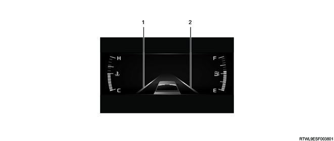
Legend
- Left lane marker
- Right lane marker
Emergency Lane Keeping (ELK)
The operating states of the ELK are displayed.

5) Illumi level display
Only when the manual illumination mode is selected, this item is displayed on the MID. The instrument panel cluster and MID brightness can be separately adjusted in 6 levels.


6) Settings
The following meter settings can be changed.
- Language
- Maintenance settings
- Meter settings
- Clock
- Calendar
- Illumination mode
- Body electrical settings
- Driving support settings
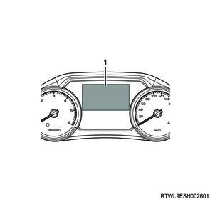
5. Liquid crystal display (LCD)
The LCD has the ability to display the following information.
The trip knob operation enables the display switching and other operations.
Legend
- Liquid crystal display (LCD)
Legend
- Trip knob
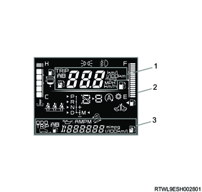
Legend
- Display area 1
- Display area 2
- Display area 3
1) Display area 1
When the odometer is displayed on Display area 3, pressing and holding the trip knob can switch the following displays.
- Fuel efficiency
- Vehicle speed
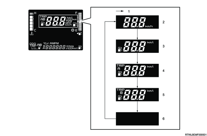
Legend
- Press the trip knob once.
- Vehicle speed
- Instantaneous fuel efficiency
- Trip meter A average fuel efficiency
- Trip meter B average fuel efficiency
- OFF
2) Display area 2
- Engine coolant temperature gauge
- Fuel gauge
- Warning light
- Indication light
- Gear shift indicator (GSI)
3) Display area 3
- Odometer
- Trip meter
- Fuel efficiency
- Possible travel distance
- Calendar
- Clock
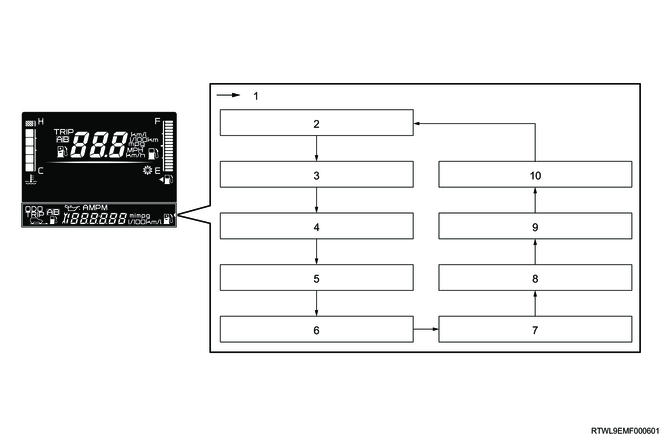
Legend
- Press the trip knob once.
- Odometer
- Trip meter A
- Trip meter A average fuel efficiency
- Trip meter B
- Trip meter B average fuel efficiency
- Instantaneous fuel efficiency
- Possible travel distance
- Calendar display
- Clock display
6. Gear shift indicator (GSI)
The gear shift indicator (GSI) is a function that assists fuel efficient driving. For manual transmission models, it shows the current and recommended gear positions on the display in the instrument panel cluster based on driving information (vehicle speed, engine speed, or clutch conditions, etc.) sent from the ECM or TCM to the instrument panel cluster via CAN communication.
1) Gear shift indicator (GSI) display
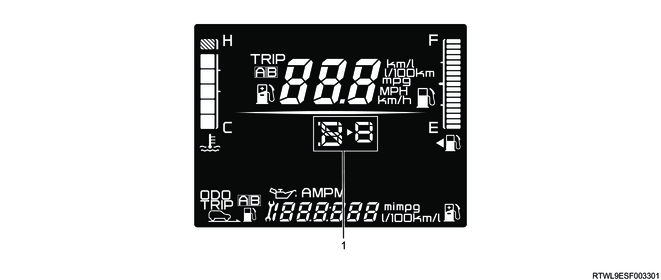
Legend
- Gear shift indicator (GSI)
2) Gear shift indicator (GSI) display method
When the possible travel distance is displayed on Display area 3, pressing and holding the trip knob can change it to one of the following 3 patterns.
- The current and recommended gear positions are displayed.
- The current and recommended gear positions are not displayed.
- Only the current gear position is displayed.
5. Glass, Windows, Mirrors
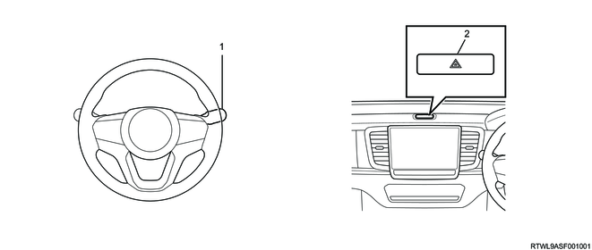
1. Room mirror with automatic anti-glare function
The room mirror with automatic anti-glare function detects the surrounding brightness by each sensor and automatically activates the anti-glare function. When the ignition switch is ON and the automatic anti-glare mode is ON, day and night determination is performed based on the brightness detected by the ambient light sensor. If it is determined that it is daytime or the auto-glare mode is OFF, the automatic anti-glare function is not activated. If it is determined that it is nighttime, the automatic anti-glare function is activated when the light from the rear is brighter than the ambient light.
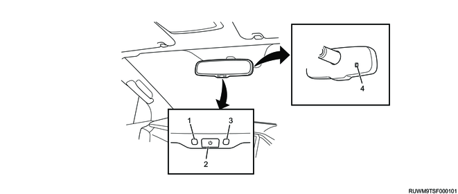
Legend
- Indicator
- Automatic anti-glare mode switch
- Rear light sensor
- Ambient light sensor
By applying a voltage to the gel contained inside the mirror, the reflectivity of the mirror is adjusted to reduce glare. The reflectivity of the mirror is steplessly adjusted according to the difference between the amounts of light detected by the rear light sensor and the ambient light sensor.
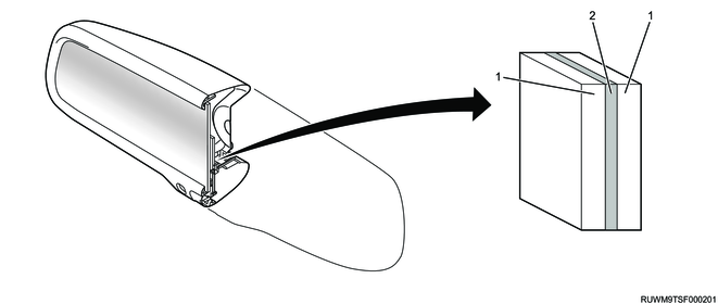
Legend
- Mirror
- Gel
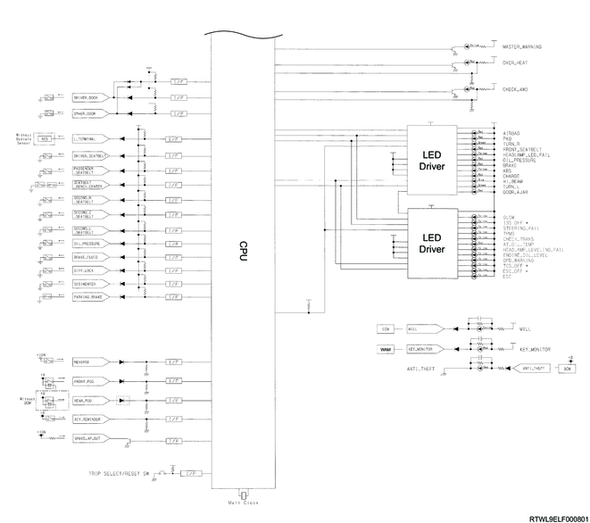
6. General circuit diagram
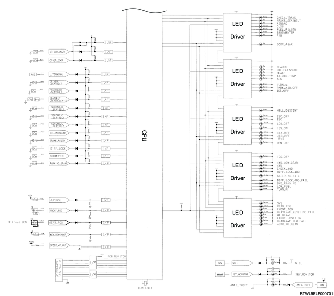
1. Instrument panel cluster system circuit diagram
Models with MID

Models with LCD