1. Component views
Relief valve
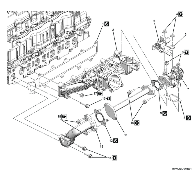
Part name
- Gasket
- Inlet cover
- Relief valve control solenoid valve
- Nut
- Relief valve control solenoid valve bracket
- Nut
- Relief valve
- Gasket
- Gasket
- Bolt
- EGR pipe
- Gasket
- EGR duct
- Bolt
- Bolt
- Bolt
- Nut
Tightening torque
4: 25 N・m { 2.5 kgf・m / 18 lb・ft }
6: 25 N・m { 2.5 kgf・m / 18 lb・ft }
10: 25 N・m { 2.5 kgf・m / 18 lb・ft }
14: 25 N・m { 2.5 kgf・m / 18 lb・ft }
15: 25 N・m { 2.5 kgf・m / 18 lb・ft }
16: 25 N・m { 2.5 kgf・m / 18 lb・ft }
17: 25 N・m { 2.5 kgf・m / 18 lb・ft }
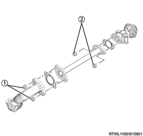
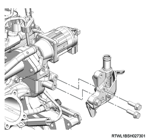
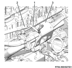
2. Relief valve installation
1. Except for Euro2 and Euro4 specifications
Caution
- Do not reuse the gasket.
1) Temporarily tighten the following parts to the EGR pipe in the order shown in the diagram.
- EGR duct
- Relief valve
- Gasket
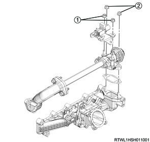
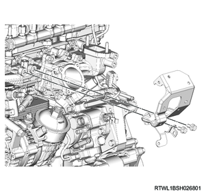
2) Temporarily tighten the following parts to the inlet cover in the order shown in the diagram.
- Relief valve
- Relief valve control solenoid valve
- Relief valve control solenoid valve bracket
- Adapter
- Gasket
3) Final tighten the following parts to the EGR pipe in the order shown in the diagram.
- EGR duct
- Relief valve
- Gasket
Tightening torque: 25 N・m { 2.5 kgf・m / 18 lb・ft }
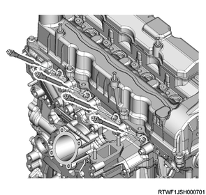
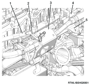
4) Final tighten the following parts to the cylinder head and inlet cover in the order shown in the diagram.
- Relief valve
- Relief valve control solenoid valve
- Relief valve control solenoid valve bracket
- Adapter
- Gasket
Tightening torque: 25 N・m { 2.5 kgf・m / 18 lb・ft }
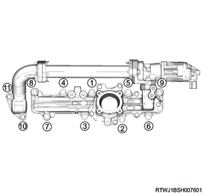
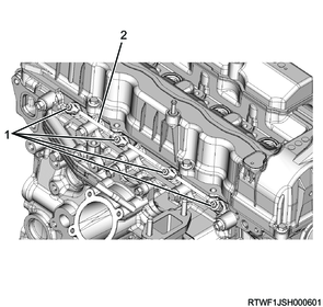
3. Inlet cover installation
1) Install the inlet cover and EGR to the cylinder head in the order shown in the diagram.
Tightening torque: 25 N・m { 2.5 kgf・m / 18 lb・ft }
2) Install the harness bracket to the inlet cover.
Note
- Install the harness bracket so that the detent makes full contact with the inlet cover.
Tightening torque: 25 N・m { 2.5 kgf・m / 18 lb・ft }

Legend
- Inlet cover
- Detent
3) Install the air duct bracket to the inlet cover.
Tightening torque: 25 N・m { 2.5 kgf・m / 18 lb・ft }
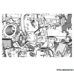
4. Glow plug installation
1) Install the glow plug to the cylinder head.
Tightening torque: 17.5 N・m { 1.8 kgf・m / 13 lb・ft }
2) Install the glow plug terminal and glow plug connector to the glow plug.
Tightening torque: 1.0 N・m { 0.10 kgf・m / 8.9 lb・in }
Legend
- Glow plug terminal
- Glow plug connector
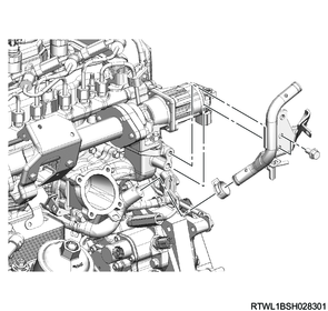
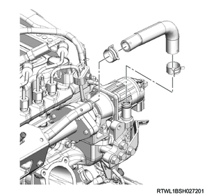
5. Water pipe installation
1) Install the water pipe to the inlet cover.
Tightening torque: 25 N・m { 2.5 kgf・m / 18 lb・ft }
Manual transmission models
Automatic transmission models
2) Install the pipe clip to the water pipe.
Tightening torque: 25 N・m { 2.5 kgf・m / 18 lb・ft }
3) Install the water pipe to the air duct bracket.
Tightening torque: 10.0 N・m { 1.0 kgf・m / 89 lb・in }
4) Install the water hose to the water pipe.
Manual transmission models

Automatic transmission models
5) Install the vacuum pipe to the air duct bracket.
Tightening torque: 10.0 N・m { 1.0 kgf・m / 89 lb・in }
6) Connect the vacuum hose to the vacuum pipe.
Euro2 specifications
Legend
- Vacuum pipe
- Vacuum hose
- Bracket
Except for Euro2 specifications
Legend
- Vacuum hose
- Vacuum pipe
- Bracket
- Relief valve control solenoid valve
- Relief valve control solenoid valve bracket
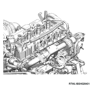
6. Oil level gauge guide tube installation
1) Apply engine oil to the O-ring.
2) Install the oil level gauge guide tube to the crankcase.
Tightening torque: 25 N・m { 2.5 kgf・m / 18 lb・ft }
3) Install the oil level gauge to the oil level gauge guide tube.
7. Intake throttle valve installation
1) Install the intake throttle valve and gasket to the inlet manifold.
Caution
- Do not reuse the gasket.
Tightening torque: 10.0 N・m { 1.0 kgf・m / 89 lb・in }
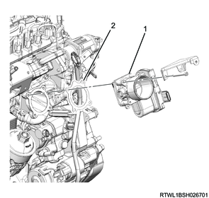
Legend
- Intake throttle valve
- Gasket
2) Connect the connector to the intake throttle valve.
8. Intake air duct installation
1) Install the intake duct to the intake throttle valve.
Tightening torque: 10.0 N・m { 1.0 kgf・m / 89 lb・in } Bolt
Tightening torque: 4.0 N・m { 0.4 kgf・m / 35 lb・in } Clamp (Intake throttle side)
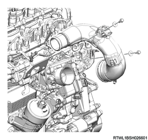
Clamp installation direction
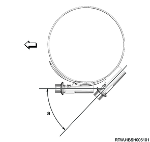
Standard value
a: 45 °
2) Connect the connector to the boost pressure and CAC temperature sensor.
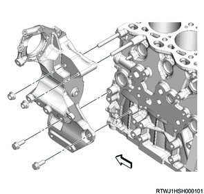
9. Generator bracket installation
1) Install the generator bracket to the cylinder block.
Tightening torque: 52 N・m { 5.3 kgf・m / 38 lb・ft }
10. A/C compressor connect
1) Connect the A/C compressor to the generator bracket.
Tightening torque: 51 N・m { 5.2 kgf・m / 38 lb・ft }
2) Connect the pipe clip to the air duct bracket.