1. Valve guide inspection
1) Inspect the valve stem and valve guide inner diameter section for the following.
- Scratches
- Abnormal wear
Note
- Replace the valve and valve guide as a set if a malfunction is found.
2. Valve inspection
1. Valve stem measurement
1) Measure the diameter of the valve stem using a micrometer.
Standard: 6.955 to 6.970 mm { 0.27382 to 0.27441 in } Inlet valve
Limit: 6.935 mm { 0.27303 in } Inlet valve
Standard: 6.947 to 6.962 mm { 0.27350 to 0.27409 in } Exhaust valve
Limit: 6.920 mm { 0.27244 in } Exhaust valve
Note
- Replace the valve and valve guide as a set if the measured value exceeds the limit.
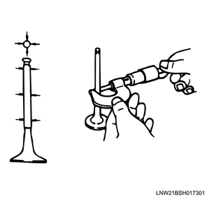
2. Clearance measurement between valve guide and valve stem
1) Measure the clearance between the valve guide and the valve stem within the range of the measuring points from the valve guide using a dial gauge.
Standard: 0.030 to 0.060 mm { 0.00118 to 0.00236 in } Inlet valve
Limit: 0.200 mm { 0.00787 in } Inlet valve
Standard: 0.038 to 0.068 mm { 0.00150 to 0.00268 in } Exhaust valve
Limit: 0.025 mm { 0.00098 in }
Note
- Replace the valve and valve guide as a set if the measured value exceeds the limit.
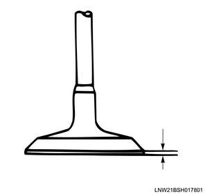
3. Valve thickness measurement
1) Measure the thickness of the valve.
Standard: 1.32 mm { 0.0520 in } Inlet valve
Limit: 1.10 mm { 0.0433 in } Inlet valve
Standard: 1.32 mm { 0.0520 in } Exhaust valve
Limit: 1.10 mm { 0.0433 in } Exhaust valve
Note
- Replace the valve and valve guide as a set if the measured value exceeds the limit.
4. Valve depth measurement
1) Remove the carbon and water deposit on the bottom surface of the cylinder head.
2) Install the valve to the cylinder head.
3) Using a depth gauge or a simple straight ruler, measure the valve depth from the cylinder head lower surface.
Standard: 0.5 mm { 0.020 in }
Limit: 1.2 mm { 0.047 in }
Note
- Replace the valve seat or cylinder head if the measured value exceeds the limit.
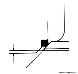
5. Valve seat contact surface measurement
1) Measure the valve seat contact surface.
Standard: 2.2 mm { 0.087 in } Inlet valve
Limit: 3.0 mm { 0.118 in } Inlet valve
Standard: 2.2 mm { 0.087 in } Exhaust valve
Limit: 3.0 mm { 0.118 in } Exhaust valve
Note
- If the contact surface is damaged or rough, repair the valve seat.
- Replace the valve seat if the measured value exceeds the limit.

3. Valve spring inspection
1. Visual inspection
1) Inspect the valve spring for the following.
- Damage
- Wear
Note
- If an abnormal condition is found, replace the valve spring.
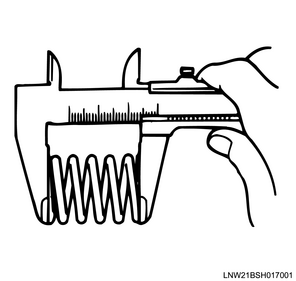
2. Valve spring free length measurement
1) Measure the free length of the valve spring using a vernier caliper.
Note
- Replace the valve spring if the measured value exceeds the limit.
Standard: 49.04 mm { 1.9307 in }
Limit: 48.15 mm { 1.8957 in }
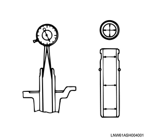
3. Valve spring perpendicularity measurement
1) Measure the perpendicularity of the valve spring using a right-angle gauge.
Note
- Replace the valve spring if the measured value exceeds the limit.
Limit: 2.1 mm { 0.083 in }

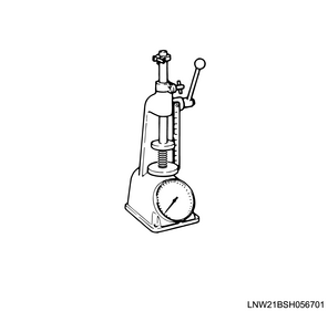
4. Valve spring installation load measurement
1) Install the valve spring to load test equipment.
Standard: 37.8 mm { 1.488 in } Installation height
Note
- Replace the valve spring if the measured value exceeds the limit.
Standard: 213 N { 21.7 kg / 48 lb }
Limit: 188 N { 19.2 kg / 42 lb }
4. Valve seat insert inspection
1. Cleaning
1) Remove the carbon from the valve seat insert surface.
2. Visual inspection
- Scratches
- Uneven sections
Note
- If there are scratches or uneven sections, adjust the valve seat insert.
3. Valve seat insert adjustment
1) Adjust the valve seat to the standard value using a seat cutter.
Note
- Minimize scratches and other uneven sections to adjust the contact width to the specified value.
Caution
- Get rid of only the scratches and uneven portions, but be careful not to over-cut.
- Use an adjustable valve cutter pilot.
- The valve cutter pilot should not be allowed to scrape inside the valve guide.
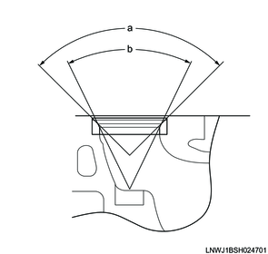
Standard value
a: 90 ° Angle 1
b: 50 ° Angle 2
2) Add compound to the valve seat surface and gently tap the valve while turning it.
Caution
- Confirm that there is even contact around the entire circumference.
- After fitting, completely remove the compound.

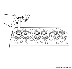
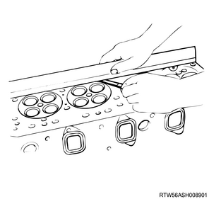
5. Cylinder head inspection
1) Measure the deformation of the cylinder block installation surface using a simple straight ruler and feeler gauge.
Note
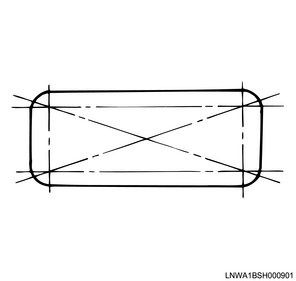
- Referring to the diagram, measure the 4 sides and across opposite corners.
- If the measured value exceeds the limit, replace the cylinder head.
Caution
- Do not polish the cylinder head lower surface.
Standard: 0.05 mm or less { 0.0020 in or less }
Limit: 0.20 mm { 0.0079 in }
2) Measure the deformation of the exhaust manifold installation surface using a simple straight ruler and feeler gauge.
Note
- Measure the 4 sides and across opposite corners.
Standard: 0.05 mm or less { 0.0020 in or less }
Limit: 0.20 mm { 0.0079 in }
0.40 mm { 0.0157 in } Repair limit
