1. Engine control system overview
The engine control system is an electronic control system that controls the engine in order to constantly provide an optimal combustion state according to the driving conditions. The ECM primarily uses the information from each sensor to control the following items.
- Electronically controlled fuel injection system
- EGR
- Turbocharger control
- DPD
ECM input/output diagram
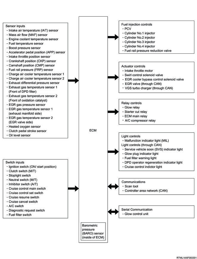
Note
- The components connected to the ECM may vary depending on the vehicle specifications.
2. Fuel system description
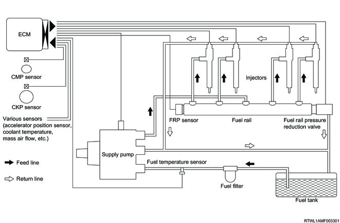
1. System overview
The common rail (fuel rail) system contains an accumulator known as a common rail (fuel rail) to store pressurized fuel, and an injector with electronic control solenoid valve to inject the pressurized fuel into the combustion chamber. Injection control (injection pressure, injection rate, and injection timing) is controlled by the ECM, and thus the common rail (fuel rail) system can be controlled independently, free from the influence of engine speed and load. This ensures stable injection pressure at all times, particularly in the low engine speed range, and therefore significantly reduces the black smoke specific to diesel engines generated during engine starting or acceleration. As a result, the cleanliness and volume of exhaust gas are improved and higher output can be achieved.
2. Injection pressure control
High-pressure injection is enabled even in low engine speed ranges.
Control for minimizing particulate matter and NOx emissions is optimized.
3. Injection timing control
Finely tuned optimized control in accordance with running conditions is enabled.
4. Injection rate control
Pre-injection control for injecting a small amount of fuel before the main injection
The primary components of the common rail (fuel rail) system are the fuel supply pump, fuel rail, injector, and ECM.
5. Fuel injection quantity control
This control determines the fuel injection quantity by using the ECM to calculate the basic injection quantity, engine coolant temperature, fuel temperature, intake air temperature, and some switch input information according to the engine operating conditions. When the accelerator pedal is depressed to a predetermined engine speed, engine load increases and more fuel is required. By controlling the micronized fuel in combination with high-pressure injection, exhaust gases can be refined and fuel consumption reduced. Compared with conventional mechanical controllers, an electronic control system allows more freedom in the fuel injection quantity control for more precise accelerator response.
6. Start-up injection quantity control
When the engine is started, the proper fuel injection quantity is controlled based on the engine speed and engine coolant temperature. At low temperatures, the fuel injection quantity increases. When the engine is started completely, the boosted quantity mode at startup is canceled and the normal running mode is restored.
7. Idle speed control
Control is performed in order to achieve a stable idle speed at all times regardless of changes to the engine over time or variations in engine condition. The ECM sets the target idle speed and controls the fuel injection quantity according to the engine conditions so that the actual engine speed remains close to the target idle speed, ensuring a stable idle speed.
8. Idling vibration control
Engine vibration caused by torque variations between cylinders resulting from variability in injector performance or fuel injection quantities at different cylinders is reduced. The ECM corrects the injection quantity between cylinders based on the revolution signals from the CKP sensor. The normal range of correction quantity between cylinders is within -5 to 5 mm3.
9. Correction value learning for small fuel injection quantity
The ECM corrects the difference between the desired injection quantity and the actual injection quantity due to time-related deterioration, etc., in order to improve accuracy during small fuel injection quantity. This correction allows drivability improvement and engine noise (combustion noise) reduction effect. During the correction value learning for small fuel injection quantity, the ECM performs injection of a small amount of fuel during deceleration (when no fuel is injected) and determines the correction amount by detecting the change of engine speed generated from the fuel injection.
Note
- If the injector is replaced, it is necessary to reset the learned values using the scan tool.
3. EGR system
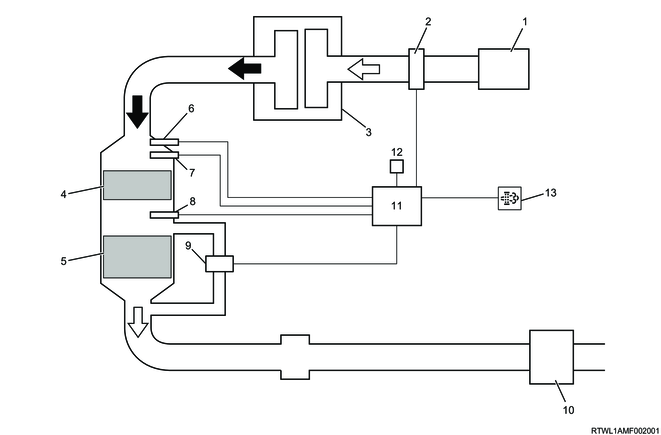
1. EGR system
The EGR system recirculates a part of the exhaust gas back into the inlet manifold, which results in reduced nitrogen oxide (NOx) emissions.
Higher maneuverability and emission reduction are both realized by controlling the EGR system.
The EGR is activated when the specified conditions of engine speed, engine coolant temperature, intake air temperature, and barometric pressure are met.
Then, the valve opening position is calculated based on engine speed and the desired fuel injection quantity.
The calculated valve opening position is sent from the ECM to the microprocessor inside the EGR valve via CAN.
The microprocessor operates a motor according to the desired opening position, and controls the lift amount of the EGR valve. The actual valve lift amount is also fed back to the ECM in order to provide more precise control of the EGR amount.
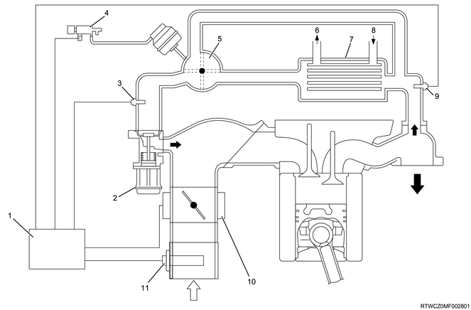
Legend
- ECM
- EGR valve
- EGR gas temperature sensor 2 (EGR valve side)
- EGR cooler bypass control solenoid valve
- EGR cooler bypass valve
- Engine coolant outlet
- EGR cooler
- Engine coolant inlet
- EGR gas temperature sensor 1 (Exhaust manifold side)
- Intake throttle valve
- MAF and IAT sensor
4. Turbocharger description
1. Turbocharger control
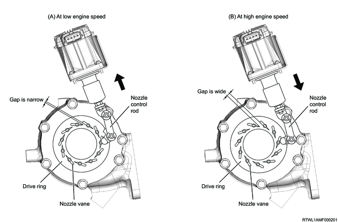
The VGS turbocharger system adjusts the opening position of the nozzle vane inside the turbocharger in order to prevent a decrease in torque at low speed ranges and ensure optimal turbo capacity at all speed ranges. The ECM sends the desired nozzle opening position to the VGS control unit, which is built into the VGS actuator, via CAN communication in order to properly control the boost pressure in accordance with the engine load requirements based on information from the boost pressure sensor and the other sensors. The VGS control unit drives the VGS actuator based on the information received from the ECM and controls the nozzle vane via the control rod.
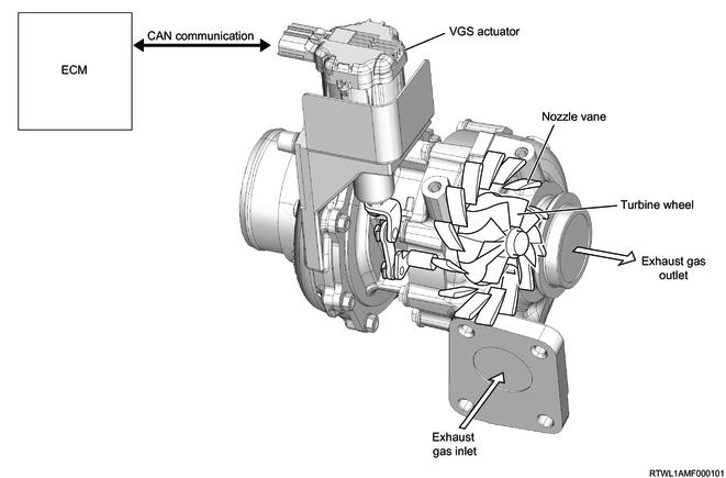
2. VGS actuator operation
The actuator is activated based on the CAN signal from the ECM, and the control rod is moved. The nozzle vane opens and closes corresponding to the movement of the control rod.
3. Nozzle vane operation
The nozzle vane opening position changes depending on the amount of the VGS actuator operation. The VGS actuator operates the drive ring via the control rod. The drive ring controls the opening position of the nozzle vane via the link depending on the engine load conditions
While the engine speed is low, the opening position of the nozzle vane decreases and the exhaust gas flow speed increases. As a result, under any driving conditions where the exhaust gas flow rate is small, the turbine speed increases and boost pressure rises.
While the engine speed is high, the opening position of the nozzle vane increases and the exhaust gas flow speed decreases. As a result, under any driving conditions where the exhaust gas flow rate is large, the turbine speed is controlled not to be excessively high and the appropriate boost pressure can be maintained.
5. DPD system description
1. DPD
The DPD is a filter which purifies NOx, CO, and HC using an oxidation catalyst, and traps PM emitted from the engine. Regeneration (burning off of PM) is performed when PM has accumulated in the filter. The ECM detects the PM accumulation status from the exhaust differential pressure sensor or from the distance the vehicle has been driven. Regeneration is performed automatically when a certain level of PM has accumulated or when the vehicle has been driven a certain distance. If automatic regeneration cannot be completed by running the vehicle, etc., the DPD operator regeneration indicator light will flash in the instrument panel cluster, requesting the driver to perform DPD regeneration. During regeneration, the temperature inside the filter is increased to burn off the accumulated PM. The ECM detects the exhaust temperature using the exhaust gas temperature sensor in order to adjust to the optimum temperature. It then increases the temperature by controlling the fuel injection in order to burn off the accumulated PM. Once regeneration is started, it must be completed within a predetermined amount of time. After regeneration has been completed, it is possible to determine the purification of the filter by checking the exhaust differential pressure.
Legend
- Air cleaner
- MAF and IAT sensor
- Engine assembly
- Oxidation catalyst
- DPD filter
- Heated oxygen sensor
- Exhaust gas temperature sensor 2
- Exhaust gas temperature sensor 1
- Exhaust differential pressure sensor
- Exhaust silencer
- ECM
- Various inputs
- DPD operator regeneration indicator light
6. ECM
1. ECM
The ECM constantly monitors the information sent from various sensors and controls each system of the powertrain. The ECM performs the diagnostic functions of the system, detects operational problems with the system, warns the driver via the MIL, and stores DTCs. The DTC identifies the areas where problems have occurred to assist the repair operation performed by the technician.
2. ECM voltage description
The ECM applies the specified voltage to various switches and sensors. The ECM is able to apply voltage in such a way because the ECM resistance is very high, and the voltage that is actually applied to the circuit is low. Therefore, the test lamp may not illuminate even if it is connected to the circuit. The voltmeter that is normally used at maintenance factories may not display a correct reading because its input impedance is too low. An accurate voltage reading can be obtained by using a DMM with an input impedance of 10 MΩ. The input/output devices in the ECM include analog-to-digital converters, signal buffers, counters, and special drivers. The ECM uses electronic switches to control most components.
7. Engine controls components
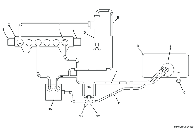
1. Fuel supply pump
The fuel supply pump is the main part of the common rail (fuel rail) type electronic fuel injection system. The fuel supply pump is installed to the front side of the engine. The PCV and feed pump are components of the fuel supply pump. By the internal feed pump, fuel is sent from the fuel tank to the fuel supply pump. The fuel is fed into the plunger chamber that is located inside the fuel supply pump. As the engine runs, this plunger force-feeds high pressure fuel to the fuel rail. The fuel force-fed to the fuel rail is adjusted by the PCV. The PCV is controlled solely by the current supplied from the ECM. When no current is flowing to the solenoid during the process of force-feeding, fuel is not force-fed. On the other hand, when current is flowing to the solenoid, the suction valve is closed and fuel is force-fed. By controlling the PCV, The ECM changes the amount of fuel supplied to the fuel rail to adjust the pressure in the fuel rail.

Legend
- Suction pressure
- Feed pressure
- High pressure
- Return pressure
- Suction valve
- PCV
- Discharge valve
- Fuel rail
- Injector
- Fuel tank
- Fuel filter
- Fuel outlet
- Regulate valve
- Fuel inlet
- Feed pump
- Camshaft
- Roller
- Shoe
- Plunger
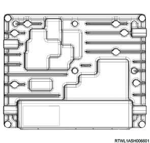
2. PCV (Pump control valve)
The PCV is installed to the fuel supply pump and it opens and closes the fuel suction valve.
The ECM changes the PCV drive timing in accordance with the desired fuel pressure commanded values and it controls the fuel discharge amount.

Legend
- PCV
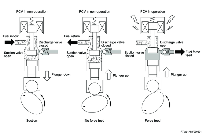
3. PCV operation
1) Suction
While the plunger is moved down, the fuel suction valve is open because the PCV is not driven, and the low pressure fuel force-fed from the feed pump flows into the plunger chamber.
2) No force feed
When the PCV is not driven even though the plunger starts moving up, the fuel flown into the plunger chamber returns to the suction side, not being pressurized.
3) Force feed
When the PCV is driven and the fuel suction valve is closed while the plunger is being moved up, the fuel pressurization starts. When the pressure of the pressurized fuel exceeds both the fuel rail pressure and discharge valve spring force, the discharge valve opens and fuel is supplied to the fuel rail.
4. Fuel rail (common rail)
Along with the employment of a common rail (fuel rail) type electronic control fuel injection system, a fuel rail is provided between the fuel supply pump and the injectors in order to store highly pressurized fuel. The FRP sensor and FRP reduction valve are installed to the fuel rail. The FRP sensor detects the fuel pressure inside the fuel rail, and sends signals to the ECM. Based on these signals, the ECM controls the fuel pressure inside the fuel rail using the PCV of the fuel supply pump. If the fuel pressure inside the fuel rail is too high, the pressure is adjusted by opening the FRP reduction valve.
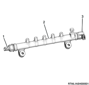
Legend
- FRP sensor
- Fuel rail
- FRP reduction valve
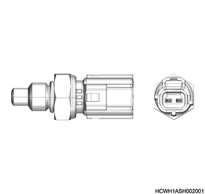
5. Fuel rail pressure (FRP) sensor
The fuel rail pressure (FRP) sensor is installed to the fuel rail. The sensor detects the fuel pressure in the fuel rail and converts the pressure to a voltage signal. The ECM monitors the FRP sensor signal voltage. The signal voltage increases as the fuel rail pressure rises, while it decreases as the pressure declines. The ECM calculates the actual fuel rail pressure from the voltage signal and uses the result in the fuel injection control and other control tasks.
6. FRP reduction valve
The fuel rail pressure (FRP) reduction valve is installed to the fuel rail. The ECM performs duty control of the linearly driven FRP reduction valve in order to decrease the fuel pressure of the fuel rail. The ECM monitors the fuel rail internal pressure, and starts to control the FRP reduction valve to decrease the fuel rail internal pressure when it rises higher than the pressure calculated by the ECM. Fuel that is relieved from the FRP reduction valve returns to the fuel tank.
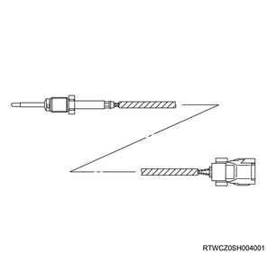
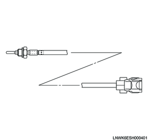
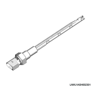
7. Fuel temperature sensor
The fuel temperature sensor is installed between the fuel filter and the fuel supply pump. The fuel temperature sensor is a variable resistor that measures the temperature of the fuel entering the fuel supply pump. When the fuel temperature is low, the fuel temperature sensor resistance is high, and when the fuel temperature becomes higher, the sensor resistance becomes lower. The ECM detects a high voltage when the sensor resistance is high, and a low voltage when the sensor resistance is low.
8. Injector
Injectors electronically controlled by the ECM consist of a solenoid valve, nozzle needle, etc. ID codes indicating the injector characteristics are written on the injectors. This system uses injector flow rate information to optimize the injection quantity control. The 2D barcode or ID code on the injector is used to improve injection quantity precision. The use of codes enables injection quantity dispersion control throughout all pressure ranges, contributing to improvements in combustion efficiency, reductions in exhaust gas emissions, and improvements in output stability. When an injector is replaced, it is necessary to input the ID code in the ECM.
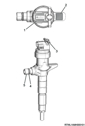
Legend
- Injector ID Code
- 2D barcode
- Fuel leak-off pipe
- O-ring
- Fuel inlet port
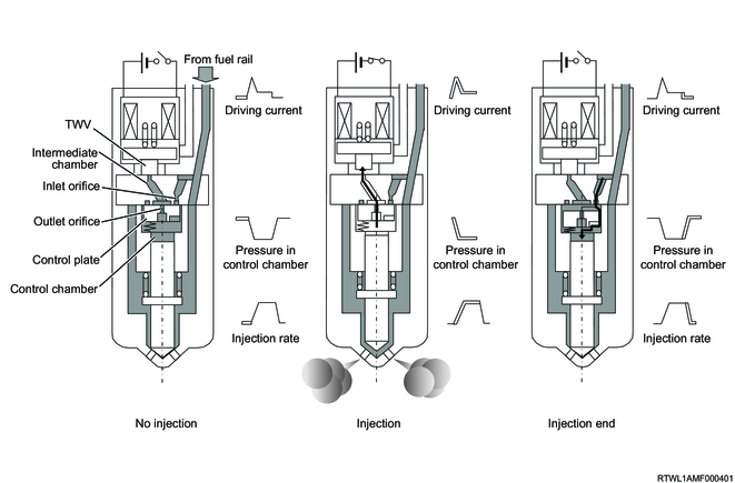
9. Injector operation
1) Non-injection state
The two-way valve (TWV) closes the intermediate chamber return port by the spring force, when no current is supplied to the solenoid from the ECM. Moreover, the control plate closes the inlet orifice by the spring force. Therefore, the fuel return becomes zero, and the fuel pressure of the intermediate chamber, control chamber and around the nozzle becomes even. At this time, the nozzle is pressed down by the spring force and fuel pressure in the control chamber, and the injection hole is closed.
2) Injection start
When the ECM supplies current to the solenoid, the two-way valve is pulled upwards, opening the intermediate chamber return port and causing fuel in the control chamber to flow from the outlet orifice to the return port. As a result, the fuel pressure in the control chamber is decreased, and the fuel pressure applied to the nozzle leading end is to be greater than the spring force and the injection hole is open to inject the fuel.
3) Injection end
When the ECM finishes supplying power to the solenoid, the two-way valve comes down and the intermediate chamber return port is closed. Due to this, the fuel pressure in the intermediate chamber increases, the control plate goes down, and the fuel flows to the control chamber from the opened inlet orifice. As a result, the nozzle is pressed down by the fuel pressure in the control chamber and the spring force, and the injection hole is closed to stop the fuel injection.
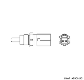
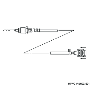
10. Engine coolant temperature sensor
The engine coolant temperature sensor is installed near the thermostat housing. The engine coolant temperature sensor is a variable resistor and measures the temperature of the engine coolant. When the engine coolant temperature is low, the engine coolant temperature sensor resistance is high, and the higher the engine coolant temperature becomes, the lower the resistance of the sensor. The ECM detects a high voltage when the sensor resistance is high, and a low voltage when the sensor resistance is low.
11. CMP sensor
The CMP sensor is installed on the timing chain sprocket cover at the front of the camshaft idle gear. The CMP sensor detects 5 projections in total per 1 engine cycle. The timing chain sprocket has 4 projections evenly spaced 90° apart and 1 reference projection. The CMP sensor is a magnetic resistance element type sensor, and generates a square wave signal pulse.
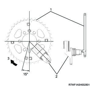
Legend
- Timing chain sprocket
- CMP sensor
- Rotational direction
12. CKP sensor
The CKP sensor is installed to the left side of the rear of the cylinder block. The sensor rotor is fixed on the crankshaft. There are 56 notches spaced 6° apart and a 30° opening. Top dead center (TDC) of cylinder No. 1 can be detected through this opening. The CKP sensor is a magnetic resistance element type sensor, and generates a square wave signal pulse. The ECM monitors the signal pulses of the CKP sensor and the CMP sensor to make sure they correlate with each other.
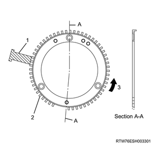
Legend
- CKP sensor
- Sensor rotor
- Rotational direction
13. Accelerator pedal position sensor
The accelerator pedal position sensor is installed as a set with the accelerator pedal. The sensor consists of 2 sensors in 1 housing. The ECM uses the accelerator pedal position sensor to calculate the desired acceleration and deceleration. The accelerator pedal position sensor is a Hall element type sensor. Each accelerator pedal position sensor sends signals related to accelerator pedal angle changes to the ECM via the signal circuit. The signal voltage of accelerator pedal position sensors 1 and 2 is kept low at first and increases as the pedal is depressed.

Legend
- Accelerator pedal position sensor
- Accelerator pedal
14. Clutch pedal stroke sensor
The clutch pedal stroke sensor is installed to the clutch master cylinder. The clutch pedal stroke sensor transmits signals related to pressure changes within the clutch master cylinder to the ECM via the signal circuit. The ECM detects the stroke amount of the clutch pedal based on the signals from the clutch pedal stroke sensor. As the clutch pedal is depressed, the clutch pedal stroke sensor signal voltage is increased.

Legend
- Clutch pedal stroke sensor
15. Barometric pressure sensor
The barometric pressure sensor is installed within the ECM and converts the barometric pressure values to voltage signals. The ECM uses this voltage signal to calibrate the fuel injection quantity and injection timing for altitude compensation.
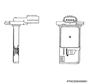
16. MAF and IAT sensor
The MAF and IAT sensor is installed to the air cleaner. The MAF and IAT sensor is one sensor comprised of a MAF sensor and IAT sensor. The MAF sensor is an air flow meter that measures the amount of air that enters the engine. The MAF sensor measures a portion of the air that passes through the duct. When the amount of air entering the engine is small, it indicates deceleration or idling speed. When the amount of air is large, it indicates acceleration or a high load state.
The IAT sensor is a variable resistor and measures the temperature of the air flowing into the engine. When the intake air temperature is low, the IAT sensor resistance is high, and the higher the intake air temperature becomes, the lower the resistance of the sensor. The ECM detects a high voltage when the sensor resistance is high, and a low voltage when the sensor resistance is low.
17. Boost pressure sensor
The boost pressure sensor is installed to the air duct. The boost pressure sensor changes the signal voltage in accordance with changes in air pressure in the air intake pipe. The boost pressure sensor transmits signals related to air pressure changes in the air intake pipe to the ECM via the signal circuit. The ECM detects a low signal voltage in low boost pressure, such as when the engine is under low load. The ECM detects a high signal voltage in high boost pressure, such as when the engine is under high load.
18. Charge air cooler temperature sensor 1, 2
Charge air cooler temperature sensor 1 is installed on the inlet side of the intercooler. Charge air cooler temperature sensor 2 is installed on the outlet side of the intercooler. Charge air cooler temperature sensors 1 and 2 are variable resistors. Charge air cooler temperature sensor 1 measures the intercooler inlet intake air temperature, and charge air cooler temperature sensor 2 measures the intercooler outlet intake air temperature. The sensor resistance is high when the intake air temperature is low, and the sensor resistance decreases as the intake air temperature increases. The ECM detects a high voltage when the sensor resistance is high, and a low voltage when the sensor resistance is low.

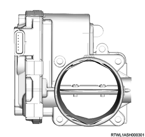
19. Intake throttle valve
The intake throttle valve is installed to the inlet manifold. The intake throttle valve is opened and closed based on the driving condition of the engine by controlling the intake throttle motor. The motor inside the intake throttle valve is controlled according to duty ratio signals sent from the ECM. The opening position of the intake throttle valve is changed in the appropriate increments from a duty ratio of 0%. The valve closes with increases in duty ratio signals and opens when duty ratio signals decrease. The intake throttle valve opening position is detected by the position sensor, and is sent to the ECM. The position sensor sends signals related to intake throttle valve position changes to the ECM via the signal circuit. The ECM detects a low signal voltage when the valve opening is small or closed. The ECM detects a high signal voltage when the valve opening is large.
20. Swirl control solenoid valve
The swirl control solenoid valve is installed to the inlet manifold via the bracket. The swirl control solenoid valve controls the vacuum supply to the swirl control actuator diaphragm based on commands from the ECM. The swirl control actuator opens and closes the butterfly of each intake port according to the vacuum controlled by the swirl control solenoid valve.

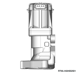
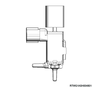
21. EGR valve
The EGR valve is installed to the inlet manifold. The ECM determines the desired opening position of the EGR valve based on the driving condition of the engine. The microprocessor inside the EGR valve controls the EGR valve by driving the motor based on the desired opening position sent from the ECM via CAN. The motor is a brushless DC motor. The EGR valve position is detected by the microprocessor inside the EGR valve, and is sent to the ECM via CAN. The ECM calculates the actual opening position of the EGR valve based on the signal received from the EGR valve.
22. EGR gas temperature sensor 1 (Exhaust manifold side)
EGR gas temperature sensor 1 (exhaust manifold side) is installed to the exhaust manifold. EGR gas temperature sensor 1 (exhaust manifold side) is a variable resistor and measures the exhaust gas temperature of the EGR cooler inlet. When the exhaust gas temperature is low, the sensor resistance of EGR gas temperature sensor 1 (exhaust manifold side) is high, and the higher the exhaust gas temperature becomes, the lower the resistance of the sensor. The ECM detects a high voltage when the sensor resistance is high, and a low voltage when the sensor resistance is low.
23. EGR gas temperature sensor 2 (EGR valve side)
EGR gas temperature sensor 2 (EGR valve side) is installed to the EGR valve adapter. EGR gas temperature sensor 2 (EGR valve side) is a variable resistor and measures the exhaust gas temperature at the EGR cooler outlet. When the exhaust gas temperature is low, the sensor resistance of EGR gas temperature sensor 2 (EGR valve side) is high, and the higher the exhaust gas temperature becomes, the lower the resistance of the sensor. The ECM detects a high voltage when the sensor resistance is high, and a low voltage when the sensor resistance is low.
24. EGR gas pressure sensor
The EGR gas pressure sensor is installed to the exhaust manifold via the adapter. The EGR gas pressure sensor transmits signals related to exhaust gas pressure changes of the EGR cooler inlet to the ECM via the signal circuit. The ECM detects a low signal voltage when the exhaust gas pressure is low. The ECM detects a high signal voltage when the exhaust gas pressure is high.

- EGR gas pressure sensor low reference
- EGR gas pressure sensor signal
- EGR gas pressure sensor 5 V reference
25. EGR cooler bypass control solenoid valve
The EGR cooler bypass control solenoid valve is installed to the inlet manifold via the bracket. When any engine coolant temperature, EGR gas temperature, engine speed, or fuel injection quantity satisfies a certain condition, the ECM controls the EGR cooler bypass control solenoid valve to adjust the vacuum. By adjusting the vacuum, it activates the EGR cooler bypass control actuator in order to open or close the EGR cooler bypass valve. When the EGR cooler bypass valve is closed, a part of the exhaust gas flows into the intake system through the EGR bypass side. When the EGR cooler bypass valve is opened, a part of the exhaust gas flows into the intake system through the EGR cooler side.
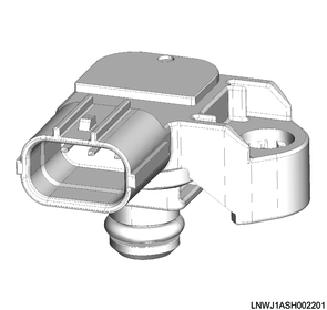
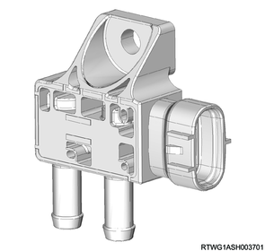
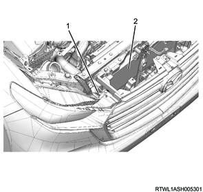
26. Exhaust differential pressure sensor
The exhaust differential pressure sensor is installed to the cylinder head cover bracket near the DPD. The exhaust differential pressure sensor changes the signal voltage in accordance with changes in the exhaust gas pressure at the front of and rear of the DPD filter. The ECM detects a low signal voltage when there is low differential pressure, such as when the PM accumulation is low. The ECM detects a high signal voltage when there is high differential pressure, such as when the PM accumulation is high. The ECM uses this signal voltage for controlling DPD regeneration or purification determination after regeneration.
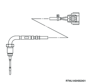
27. Exhaust gas temperature sensor 1 (Front of DPD filter)
Exhaust gas temperature sensor 1 (front of DPD filter) is installed at the inlet of the DPD filter. Exhaust gas temperature sensor 1 (front of DPD filter) is a variable resistor. Exhaust gas temperature sensor 1 (front of DPD filter) measures the exhaust gas temperature in front of the DPD filter. The sensor resistance is high when the exhaust temperature is low, and the sensor resistance decreases as the exhaust temperature increases. The ECM detects a high voltage when the sensor resistance is high, and a low voltage when the sensor resistance is low. The ECM uses this signal voltage for temperature control during DPD regeneration.
28. Exhaust gas temperature sensor 2 (Front of oxidation catalyst)
Exhaust gas temperature sensor 2 (front of oxidation catalyst) is installed near the inlet of the oxidation catalyst. Exhaust gas temperature sensor 2 (front of oxidation catalyst) is a variable resistor. Exhaust gas temperature sensor 2 (front of oxidation catalyst) measures the exhaust gas temperature in front of the oxidation catalyst. The sensor resistance is high when the exhaust temperature is low, and the sensor resistance decreases as the exhaust temperature increases. The ECM detects a high voltage when the sensor resistance is high, and a low voltage when the sensor resistance is low. The ECM uses this signal voltage for temperature control during DPD regeneration.
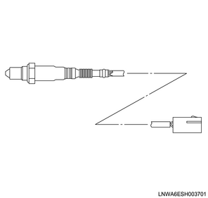
29. Heated oxygen sensor
The heated oxygen sensor is installed at the inlet of the DPD assembly. The heated oxygen sensor detects oxygen concentration in the exhaust gas. The ECM corrects the intake air amount and fuel injection quantity by comparing the air-fuel ratio calculated from the intake air amount and fuel injection quantity with the actual air-fuel ratio acquired from the signal sent from the heated oxygen sensor. The ECM performs control of the EGR so that the appropriate air amount is included in the actual injection quantity. When the heated oxygen sensor is in active status, it outputs a voltage signal generated in accordance with the oxygen concentration in the exhaust gas to the ECM. The heated oxygen sensor has a built-in heater in order to maintain its active status.
30. Oil level sensor
The oil level sensor is integrated with the oil temperature sensor, and it is installed at the left side of the crankcase. By running the rated current to the heating elements of the oil level sensor, the ECM changes the resistance.
The oil level sensor detects the engine oil level in the oil pan through the resistance of the heating elements. When the engine oil level is low, the resistance is high, and when the engine oil level is high, the resistance is low. The ECM detects a high voltage when the sensor resistance is high, and a low voltage when the sensor resistance is low. The oil temperature sensor is a variable resistor and calibrates the oil level by measuring engine oil temperature. When the engine oil temperature is low, the sensor resistance of the oil temperature sensor is high, and the sensor resistance decreases as the engine oil temperature increases. The ECM detects a high voltage when the sensor resistance is high, and a low voltage when the sensor resistance is low.
31. Glow control unit
The glow control unit is installed to the battery bracket. The glow control system operates to assist engine startup when the engine coolant temperature is low. If the ignition switch is turned ON when the engine coolant temperature is low, the ECM illuminates the glow plug indicator light via the glow control unit and turns ON the glow plugs. After a predetermined period of time passes, the ECM turns OFF the glow plug indicator light and glow plugs via the glow control unit. The glow control unit has the function to monitor the glow plug voltage and output conditions. If the glow control unit detects an open circuit in the glow plug power supply circuit or a system voltage malfunction, the glow control unit sends signals to the ECM.

32. MIL
The MIL is located in the instrument panel cluster. The symbol shown in the illustration is displayed when the MIL is ON.
When vehicle maintenance is required due to a failure related to emission, the MIL is illuminated. The following is a list of MIL operation modes.
- The MIL illuminates when the ignition switch is turned ON without starting the engine. This is a light test performed to check whether or not the MIL illuminates.
- If there is no diagnostic failure, the MIL turns OFF after the engine is started.
- If the ECM detects a failure, the MIL remains ON after the engine is started. When the ECM illuminates the MIL due to an emission-related malfunction, a DTC is stored.

33. SVS indicator light operation
The SVS indicator light is located in the instrument panel cluster. The symbol shown in the illustration is displayed when the SVS indicator light is ON.
When vehicle maintenance is required due to a non-emission-related malfunction, the SVS indicator light is displayed. The following summarizes the SVS indicator light operation.
- The SVS indicator light illuminates when the ignition switch is turned ON without starting the engine. This is a light test performed to check whether or not the SVS indicator light illuminates.
- If there is no diagnostic failure, the SVS indicator light turns OFF after the engine is started.
- If the ECM detects a failure, the SVS indicator light remains ON after the engine is started. When the ECM illuminates the SVS indicator light due to a non-emission-related malfunction, a DTC is stored.
8. Engine mechanical
1. Electronic engine control
The fuel injection quantity and injection timing are controlled by the ECM.
2. Cylinder block
The cylinder block made of cast iron and a highly rigid structure with appropriate rib location.
3. Piston
The pistons are aluminum alloy auto-thermatic pistons, and the combustion chambers are round re-entrant types.
4. Cylinder head
The cylinder head has 4 valves for each cylinder. Tighten the head bolts using the plastic region rotational angle tightening method.
5. Crankshaft
Do not adjust the crankshaft by polishing, because it is tufftrided. Therefore, the undersize bearing is not equipped. The crankshaft main bearing is selectively assembled according to the grades of the crankshaft journal outer diameter and the crankshaft bearing housing inner diameter.
6. Connecting rod cap bolt
Tighten the mounting bolt of the connecting rod cap using the plastic region rotational angle tightening method.
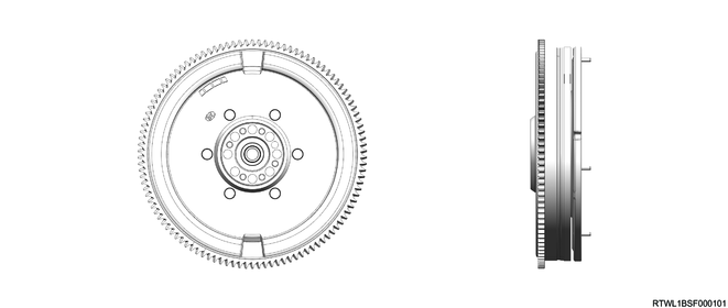
7. Dual mass flywheel (DMF)
The dual mass flywheel is composed of the primary flywheel, secondary flywheel, and arc spring.
The arc spring transmits torque from the primary flywheel to the secondary flywheel while suppressing the rotation fluctuation.
Dual mass flywheel (DMF)
9. Fuel system
1. Common rail (fuel rail) type electronically controlled injection system
The common rail (fuel rail) type control injection system is composed of a fuel supply pump that sets and supplies the desired pressure of high-pressure fuel, a fuel rail that measures the high-pressure fuel, and an injector that injects the high-pressure fuel after it has been micronized. The ECM controls the injection timing and injection quantity under various vehicle operation conditions based on various signals.
2. Fuel system diagram
Without recirculation valve

Legend
- FRP sensor
- Fuel rail
- Leak-off pipe
- FRP reduction valve
- Injector
- Fuel leak-off hose
- Fuel return pipe
- Fuel tank
- Fuel tank unit
- Fuel filler cap
- Fuel feed pipe
- Fuel filter (With sedimenter)
- Clogging switch
- Fuel supply pump
With recirculation valve
Legend
- FRP sensor
- Fuel rail
- Leak-off pipe
- FRP reduction valve
- Injector
- Fuel leak-off hose
- Fuel return pipe
- Fuel tank
- Fuel tank unit
- Fuel filler cap
- Fuel feed pipe
- Fuel filter (With sedimenter)
- Clogging switch
- Recirculation valve
- Fuel supply pump
3. Fuel filter
The fuel filter has a sedimenter to remove moisture by using the difference of the relative density of diesel oil and water, and it also has an indicator that shows water accumulation.
Without recirculation valve
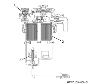
Legend
- Clogging switch
- Fuel filter element
- Sedimenter switch
With recirculation valve
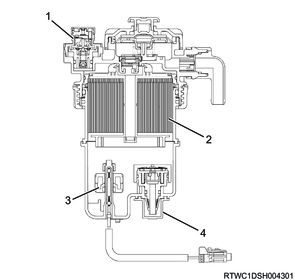
Legend
- Clogging switch
- Fuel filter element
- Sedimenter switch
- Recirculation valve
10. Cooling system
The cooling system is a force-circulation system, and its main components are the water pump, thermostat, cooling fan, and the radiator.
To quickly increase cold engine coolant temperature for smooth engine operation, the engine coolant is circulated by the water pump and the thermostat through the bypass pipe and back to the cylinder body. At this time, the engine coolant does not circulate through the radiator.
When the engine coolant temperature reaches the specified value, the thermostat begins to open to gradually increase the amount of engine coolant circulating through the radiator.
When the engine coolant temperature reaches the specified value, the thermostat is fully opened. Then all of the engine coolant circulates through the radiator to cool the engine effectively.
1. Cooling System
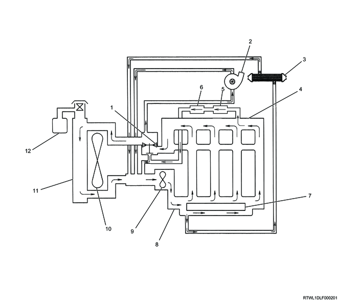
Legend
- Thermostat
- Turbocharger
- EGR cooler
- Cylinder head
- Heater core
- ATF cooler/warmer
- Oil cooler
- Cylinder block
- Water pump
- Cooling fan
- Radiator
- Reserve tank
2. Water pump
The centrifugal water pump forcibly circulates engine coolant in the cooling system.
The water pump cannot be disassembled.

3. Thermostat
The thermostat is a wax pellet type.

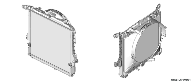
4. Radiator
The radiator is a tube type with corrugated fins. To raise the boiling point of the engine coolant, a pressurized radiator cap is attached. The radiator cap open valve pressure is 93.3 to 122.7 kPa {0.95 to 1.25 kg/cm2 / 14 to 18 psi}.
The radiator cap opens and closes using a double action mechanism.
Caution
- When removing the radiator cap, do not pull it by force, but loosen it until it cannot rotate further.
- To install the cap, turn the radiator cap until it does not turn.
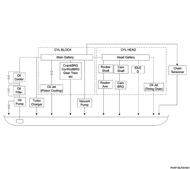
11. Lubrication system
The lubrication system uses a full-flow filter element with integrated bypass, a water-cooled oil cooler, and oil jets for cooling the pistons.
Oil is sent from the oil gallery and through the water-cooled oil cooler to lubricate each sliding section.
1. Lubricating system diagram
12. Exhaust system
The DPD unit is an integrated structure with an oxidation catalyst and filter, and performs the cleaning of exhaust gases. When a pressure difference between the front and rear of the DPD is detected, or when the vehicle is driven a set distance, trapped PM will be burned off and the filter will be regenerated.
The main components consist of the DPD, front exhaust pipe, and exhaust silencer.

Legend
- DPD
- Front exhaust pipe
- Exhaust silencer
13. Emission control devices
1. EGR system
The EGR system recirculates a part of the exhaust gas to the inlet manifold, and by mixing in inert gas to the intake air, the combustion temperature is lowered and the generation of NOx is suppressed.
The control method of this EGR employs an electronic control method that ensures both drivability and low emissions. This activates the direct current motor using a control current from the ECM to control the EGR valve.
Legend
- ECM
- EGR valve
- EGR gas temperature sensor 2 (EGR valve side)
- EGR cooler bypass control solenoid valve
- EGR cooler bypass valve
- Engine coolant outlet
- EGR cooler
- Engine coolant inlet
- EGR gas temperature sensor 1 (Exhaust manifold side)
- Intake throttle valve
- MAF and IAT sensor
14. Electrical system
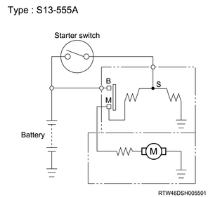
1. Starter circuit
The starting system consists of the batteries, starter, ignition switch, inhibitor switch (A/T only), starter relay, etc. Each of these main components is wired as shown in the starter circuit diagram.

Legend
- Pinion clutch
- Ring gear
- Shift lever
- Magnetic switch
- S-terminal
- B-terminal
- Inhibitor switch (For A/T only)
- Starter relay
- Ignition switch
- Battery
- Armature
Starter circuit diagram
2. Starter
The 1.8 kW starter motor is a gear reduction type. The starter is constructed of the main assembly (starter housing, starter magnetic switch assembly, starter yoke assembly, and starter end frame). The starter magnetic switch assembly encloses the starter clutch sub-assembly. The starter yoke assembly includes the starter armature. The starter end frame encloses the rear of the starter yoke with the 2 bolt-throughs installed to the starter housing.
Starter motor
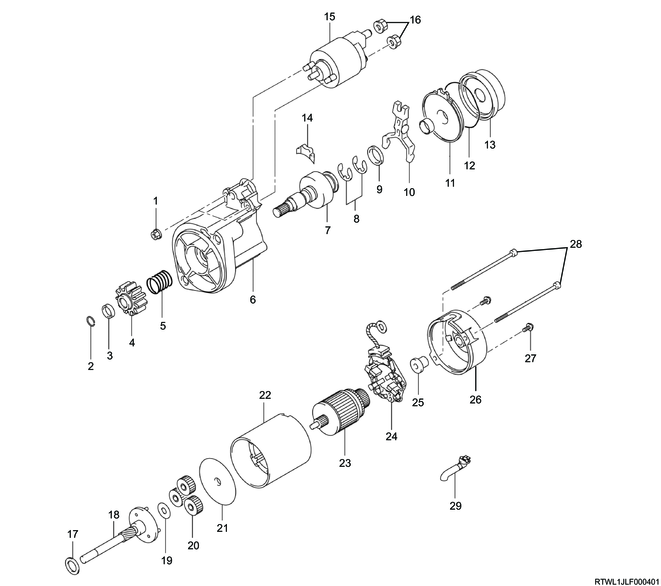
Legend
- Nut
- Snap ring
- Nut
- Pinion
- Spring
- Housing
- Clutch
- Washer
- Washer
- Shift lever
- Bearing
- Starter spring
- Internal gear
- Seal
- Magnetic switch
- Nut
- Washer
- Clutch shaft
- Washer
- Planetary gear
- Plate
- Yoke
- Armature
- Brush holder
- Bearing
- Rear cover
- Screw
- Through bolt
- Drain bushing
3. Generator
The charging system uses an IC integral regulator charging method. The main components are connected as shown in the diagram. The regulator is an integrated solid-state type regulator. It is built into the generator, and installed onto the rear end cover together with the brush holder.
Generator maintenance such as adjusting the voltage is not required. There are 6 diodes in the rectifier connected to the stator coil. They convert AC voltage into DC voltage. The direct current voltage is connected to the generator output terminal.
The generator cannot be disassembled.
Generator

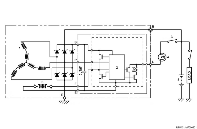
Legend
- Stator coil
- IC regulator
- Key switch
- Charge light
- Battery
- Rotor coil
15. Engine controls component views
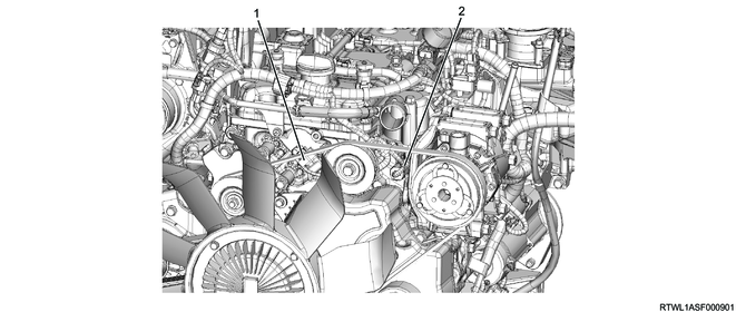
1. Engine component location diagram
Legend
- Accelerator pedal position sensor
- Accelerator pedal

Legend
- Clutch pedal stroke sensor
- Clutch pedal
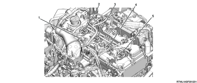
Legend
- Charge air cooler temperature sensor 2
- Cylinder No. 1 injector
- Cylinder No. 2 injector
- Cylinder No. 3 injector
- Cylinder No. 4 injector
Legend
- CMP sensor
- Engine coolant temperature sensor
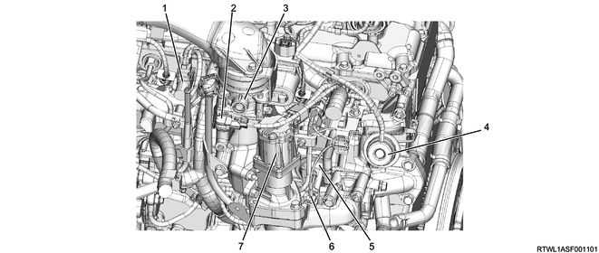
Legend
- Swirl control solenoid valve
- Boost pressure sensor
- Intake throttle valve
- Swirl control actuator
- EGR cooler bypass control actuator
- EGR gas temperature sensor 2 (EGR valve side)
- EGR valve
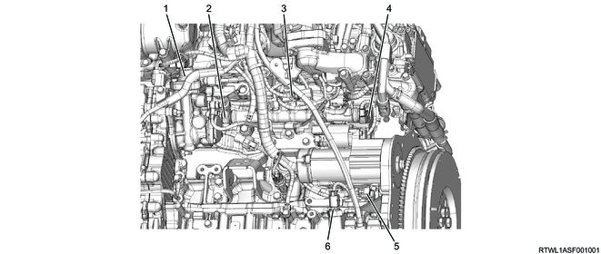
Legend
- PCV
- FRP sensor
- EGR cooler bypass control solenoid valve
- FRP reduction valve
- CKP sensor
- Oil level sensor
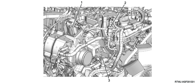
Legend
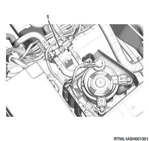
- VGS actuator
- EGR gas pressure sensor
- EGR gas temperature sensor 1 (Exhaust manifold side)
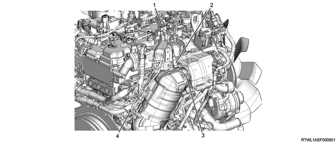
Legend
- Exhaust differential pressure sensor
- Heated oxygen sensor
- Exhaust gas temperature sensor 2 (Front of oxidation catalyst)
- Exhaust gas temperature sensor 1 (Front of DPD filter)
Legend
- Charge air cooler temperature sensor 1
- Intercooler
Legend
- Fuel temperature sensor
Legend
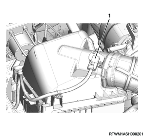
- MAF and IAT sensor
RHD models
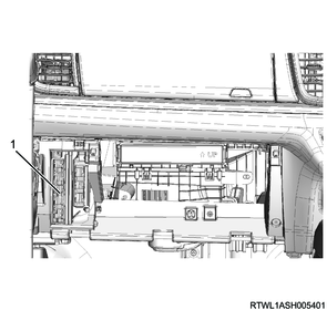
Legend
- ECM
LHD models

Legend
- ECM
Vacuum hose routing diagram
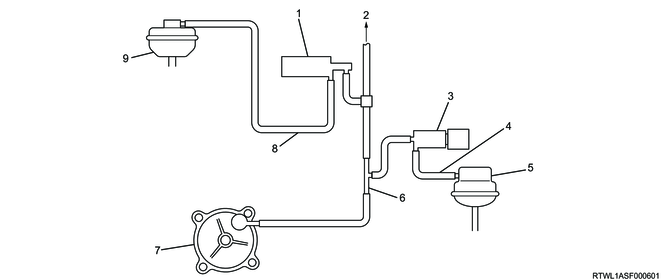
Legend
- Swirl control solenoid valve
- Brake booster
- EGR cooler bypass control solenoid valve
- Actuator control vacuum hose
- EGR cooler bypass control actuator
- Vacuum pipe
- Vacuum pump
- Actuator control vacuum hose
- Swirl control actuator
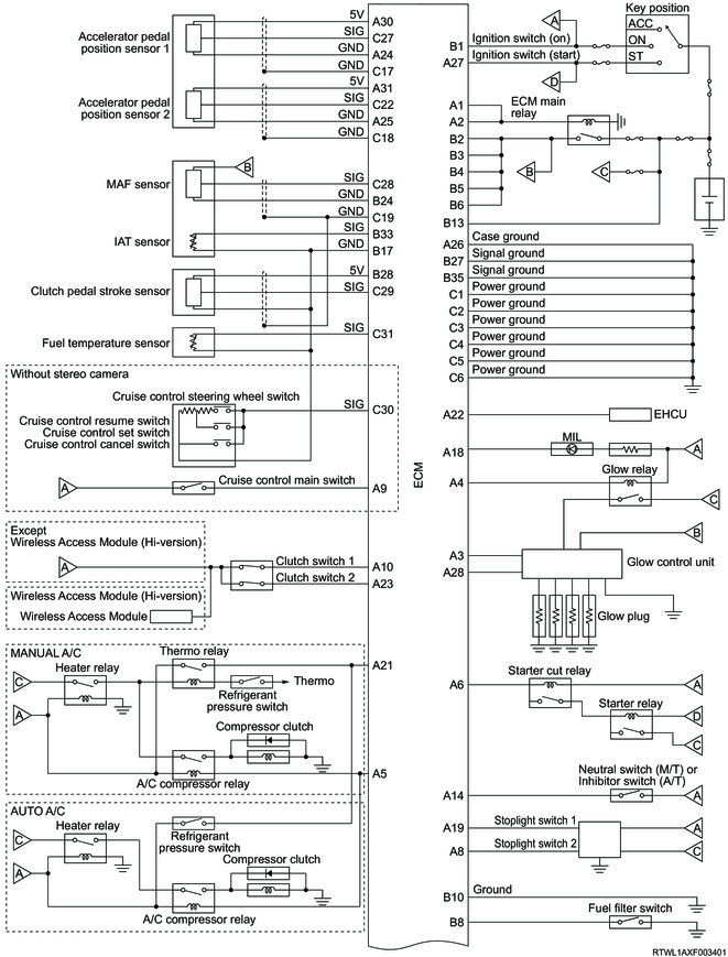
16. General circuit diagram
1. General circuit diagram
1/2
2/2
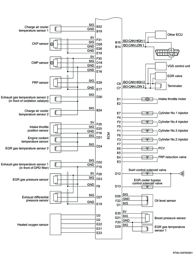
Note
- The components connected to the ECM may vary depending on the vehicle specifications.
2. ECM outline
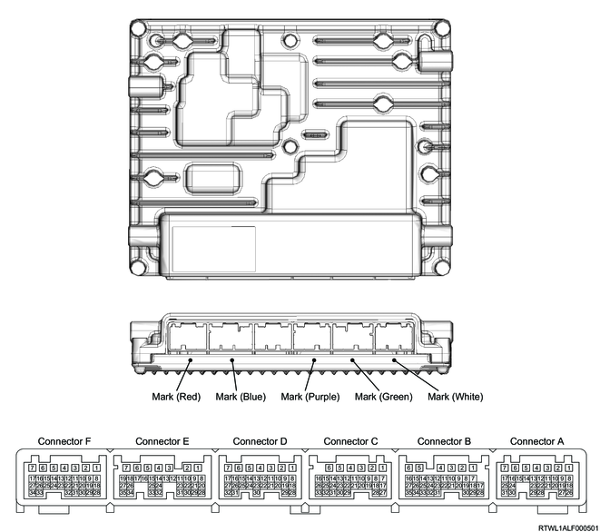
3. ECM pin layout
| PIN No. |
Pin function |
| 1 |
ECM main relay control |
| 2 |
ECM main relay control |
| 3 |
Glow plug control signal from ECM |
| 4 |
Glow relay control |
| 5 |
A/C compressor relay control |
| 6 |
Starter cut relay control |
| 7 |
- |
| 8 |
Stoplight switch 2 signal |
| 9 |
Cruise control main switch signal |
| 10 |
Clutch switch 1 signal |
| 11 |
- |
| 12 |
- |
| 13 |
- |
| 14 |
Neutral switch signal (M/T) |
| Inhibitor switch signal (A/T) |
|
| 15 |
- |
| 16 |
- |
| 17 |
- |
| 18 |
MIL control |
| 19 |
Stoplight switch 1 signal |
| 20 |
- |
| 21 |
Thermo relay signal (manual A/C) |
| Refrigerant pressure switch signal (auto A/C) |
|
| 22 |
Vehicle speed signal |
| 23 |
Clutch switch 2 signal |
| 24 |
Accelerator pedal position sensor 1 low reference |
| 25 |
Accelerator pedal position sensor 2 low reference |
| 26 |
ECM case ground |
| 27 |
Ignition voltage (start) |
| 28 |
Glow plug diagnosis signal to ECM |
| 29 |
- |
| 30 |
Accelerator pedal position sensor 1, 5 volts reference |
| 31 |
Accelerator pedal position sensor 2, 5 volts reference |
| PIN No. |
Pin function |
| 1 |
Ignition voltage (ON) |
| 2 |
Battery voltage |
| 3 |
Battery voltage |
| 4 |
Battery voltage |
| 5 |
Battery voltage |
| 6 |
Battery voltage |
| 7 |
- |
| 8 |
Fuel filter switch signal |
| 9 |
- |
| 10 |
Ground |
| 11 |
- |
| 12 |
- |
| 13 |
Battery voltage |
| 14 |
ISO CAN low 1 signal |
| 15 |
- |
| 16 |
ISO CAN high 1 signal |
| 17 |
IAT sensor, Cruise control switch, Clutch pedal stroke sensor and Fuel temperature sensor low reference |
| 18 |
- |
| 19 |
Charge air cooler temperature sensor 1 low reference |
| 20 |
- |
| 21 |
- |
| 22 |
- |
| 23 |
- |
| 24 |
MAF sensor low reference |
| 25 |
- |
| 26 |
- |
| 27 |
ECM signal ground |
| 28 |
Clutch pedal stroke sensor 5 volts reference |
| 29 |
- |
| 30 |
- |
| 31 |
- |
| 32 |
Charge air cooler temperature sensor 1 signal |
| 33 |
IAT sensor signal |
| 34 |
Charge air cooler temperature sensor 2 signal |
| 35 |
ECM signal ground |
| PIN No. |
Pin function |
| 1 |
ECM power ground |
| 2 |
ECM power ground |
| 3 |
ECM power ground |
| 4 |
ECM power ground |
| 5 |
ECM power ground |
| 6 |
ECM power ground |
| 7 |
ISO CAN low 2 signal |
| 8 |
- |
| 9 |
ISO CAN high 2 signal |
| 10 |
- |
| 11 |
- |
| 12 |
- |
| 13 |
- |
| 14 |
- |
| 15 |
- |
| 16 |
- |
| 17 |
Accelerator pedal position sensor 1 shield ground |
| 18 |
Accelerator pedal position sensor 2 shield ground |
| 19 |
MAF sensor and Clutch pedal stroke sensor shield ground |
| 20 |
- |
| 21 |
- |
| 22 |
Accelerator pedal position sensor 2 signal |
| 23 |
- |
| 24 |
- |
| 25 |
- |
| 26 |
- |
| 27 |
Accelerator pedal position sensor 1 signal |
| 28 |
MAF sensor signal |
| 29 |
Clutch pedal stroke sensor signal |
| 30 |
Cruise control switch signal |
| 31 |
Fuel temperature sensor signal |
| 32 |
- |
| 33 |
- |
| PIN No. |
Pin function |
| 1 |
Oil level sensor (oil level) signal |
| 2 |
Heated oxygen sensor heater low side |
| 3 |
Heated oxygen sensor heater high side |
| 4 |
- |
| 5 |
- |
| 6 |
- |
| 7 |
- |
| 8 |
- |
| 9 |
- |
| 10 |
- |
| 11 |
- |
| 12 |
Swirl control solenoid valve control |
| 13 |
EGR cooler bypass control solenoid valve control |
| 14 |
- |
| 15 |
- |
| 16 |
- |
| 17 |
- |
| 18 |
CMP sensor signal |
| 19 |
- |
| 20 |
- |
| 21 |
Boost pressure sensor signal |
| 22 |
- |
| 23 |
EGR gas pressure sensor signal |
| 24 |
EGR gas temperature sensor 2 signal |
| 25 |
- |
| 26 |
Oil level sensor (oil temperature) signal |
| 27 |
Exhaust differential pressure sensor signal |
| 28 |
CKP sensor signal |
| 29 |
EGR gas temperature sensor 1 signal |
| 30 |
Exhaust gas temperature sensor 2 signal |
| 31 |
Engine coolant temperature sensor signal |
| 32 |
Exhaust gas temperature sensor 1 signal |
| PIN No. |
Pin function |
| 1 |
Intake throttle motor 1 |
| 2 |
Intake throttle motor 2 |
| 3 |
FRP reduction valve low side |
| 4 |
FRP reduction valve high side |
| 5 |
PCV low side |
| 6 |
PCV high side |
| 7 |
Cylinder No. 1 injector solenoid control |
| 8 |
- |
| 9 |
- |
| 10 |
- |
| 11 |
- |
| 12 |
- |
| 13 |
- |
| 14 |
- |
| 15 |
- |
| 16 |
CMP sensor shield ground |
| 17 |
FRP sensor shield ground |
| 18 |
CKP sensor shield ground |
| 19 |
- |
| 20 |
- |
| 21 |
- |
| 22 |
Heated oxygen sensor pump current (IP) |
| 23 |
Heated oxygen sensor low reference (VM) |
| 24 |
- |
| 25 |
Intake throttle position sensor signal |
| 26 |
CKP sensor low reference |
| 27 |
CMP sensor, FRP sensor, Exhaust gas temperature sensor 2, and Charge air cooler temperature sensor 2 low reference |
| 28 |
- |
| 29 |
FRP sensor signal |
| 30 |
- |
| 31 |
Heated oxygen sensor reference voltage (UN) |
| 32 |
- |
| 33 |
- |
| 34 |
- |
| 35 |
Boost pressure sensor 5 volts reference |
| PIN No. |
Pin function |
| 1 |
Cylinder No. 3 injector solenoid control |
| 2 |
Cylinder No. 4 injector solenoid control |
| 3 |
Cylinder No. 2 injector solenoid control |
| 4 |
Cylinder No. 1 injector charge voltage |
| 5 |
Cylinder No. 4 injector charge voltage |
| 6 |
Cylinder No. 3 injector charge voltage |
| 7 |
Cylinder No. 2 injector charge voltage |
| 8 |
EGR gas pressure sensor shield ground |
| 9 |
- |
| 10 |
- |
| 11 |
- |
| 12 |
- |
| 13 |
- |
| 14 |
- |
| 15 |
- |
| 16 |
- |
| 17 |
- |
| 18 |
Intake throttle position sensor, engine coolant temperature sensor, and EGR gas temperature sensor 2 low reference |
| 19 |
Exhaust gas temperature sensor 1, EGR gas pressure sensor, and Exhaust differential pressure sensor low reference |
| 20 |
Boost pressure sensor and EGR gas temperature sensor 1 low reference |
| 21 |
- |
| 22 |
Oil level sensor low reference |
| 23 |
- |
| 24 |
- |
| 25 |
- |
| 26 |
- |
| 27 |
- |
| 28 |
EGR gas pressure sensor and Exhaust differential pressure sensor 5 volts reference |
| 29 |
Intake throttle position sensor 5 volts reference |
| 30 |
CMP sensor and FRP sensor 5 volts reference |
| 31 |
CKP sensor 5 volts reference |
| 32 |
- |
| 33 |
- |
| 34 |
- |
17. Engine number
Engine number stamping position

Legend
- Engine model
- Engine number