1. Component views
Coil spring
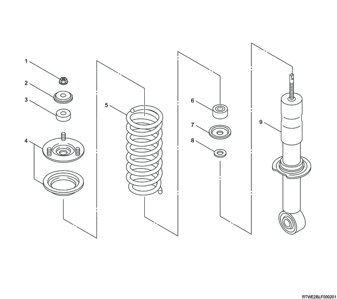
Part name
- Nut
- Washer
- Rubber bushing
- Front mount bracket
- Coil spring
- Rubber bushing
- Washer
- Washer
- Shock absorber
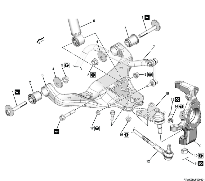
Shock absorber (2WD (Except high ride suspension specification))
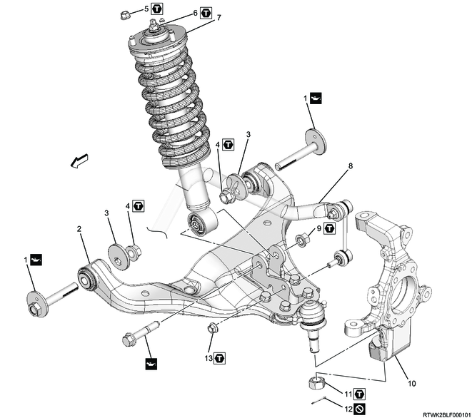
Part name
- Cam bolt
- Lower link
- Cam plate
- Nut
- Nut
- Nut
- Shock absorber assembly
- Stabilizer bar
- Nut
- Knuckle
- Nut
- Cotter pin
- Nut
Tightening torque
4: 186 N・m { 19.0 kgf・m / 137 lb・ft }
5: 55 N・m { 5.6 kgf・m / 41 lb・ft }
6: 25 N・m { 2.5 kgf・m / 18 lb・ft }
9: 152 N・m { 15.5 kgf・m / 112 lb・ft }
11: 147 N・m { 15.0 kgf・m / 108 lb・ft }
13: 64 N・m { 6.5 kgf・m / 47 lb・ft }
Stabilizer bar (2WD (Except high ride suspension specification))
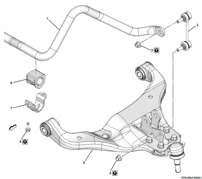
Part name
- Stabilizer bar
- Nut
- Stabilizer link
- Nut
- Lower link
- Bolt
- Clamp
- Rubber bushing
Tightening torque
2: 64 N・m { 6.5 kgf・m / 47 lb・ft }
4: 64 N・m { 6.5 kgf・m / 47 lb・ft }
6: 47.1 N・m { 4.8 kgf・m / 35 lb・ft }
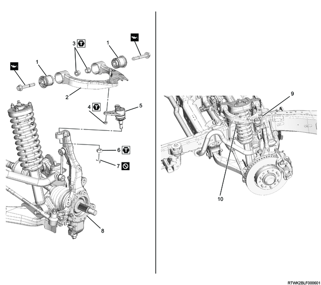
Upper link (2WD (Except high ride suspension specification))
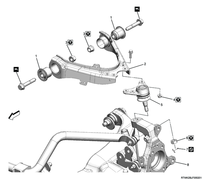
Part name
- Bushing
- Upper link
- Nut
- Nut
- Upper ball joint
- Nut
- Cotter pin
- Knuckle
Tightening torque
3: 137 N・m { 14.0 kgf・m / 101 lb・ft }
4: 31.4 N・m { 3.2 kgf・m / 23 lb・ft }
6: 98 N・m { 10.0 kgf・m / 72 lb・ft }
Lower link (2WD (Except high ride suspension specification))
Part name
- Cam bolt
- Bushing
- Lower link
- Cam plate
- Nut
- Shock absorber
- Stabilizer bar
- Nut
- Knuckle
- Nut
- Cotter pin
- Tie rod end
- Cotter pin
- Nut
- Lower ball joint
- Nut
- Nut
Tightening torque
5: 186 N・m { 19.0 kgf・m / 137 lb・ft }
8: 152 N・m { 15.5 kgf・m / 112 lb・ft }
10: 147 N・m { 15.0 kgf・m / 108 lb・ft }
14: 98 N・m { 10.0 kgf・m / 72 lb・ft }
16: 126.5 N・m { 12.9 kgf・m / 93 lb・ft }
17: 64 N・m { 6.5 kgf・m / 47 lb・ft }
Bumper rubber (2WD (Except high ride suspension specification))
Part name
- Bumper rubber
- Bolt
Tightening torque
2: 51 N・m { 5.2 kgf・m / 38 lb・ft }
Shock absorber (2WD (High ride suspension specification), 4WD)
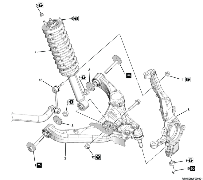
Part name
- Cam bolt
- Lower link
- Cam plate
- Nut
- Nut
- Nut
- Shock absorber assembly
- Knuckle
- Nut
- Cotter pin
- Nut
- Nut
- Stabilizer link
Tightening torque
4: 186 N・m { 19.0 kgf・m / 137 lb・ft }
5: 55 N・m { 5.6 kgf・m / 41 lb・ft }
6: 25 N・m { 2.5 kgf・m / 18 lb・ft }
9: 147 N・m { 15.0 kgf・m / 108 lb・ft }
11: 97.1 N・m { 9.9 kgf・m / 72 lb・ft }
12: 152 N・m { 15.5 kgf・m / 112 lb・ft }
Stabilizer bar (2WD (High ride suspension specification), 4WD)
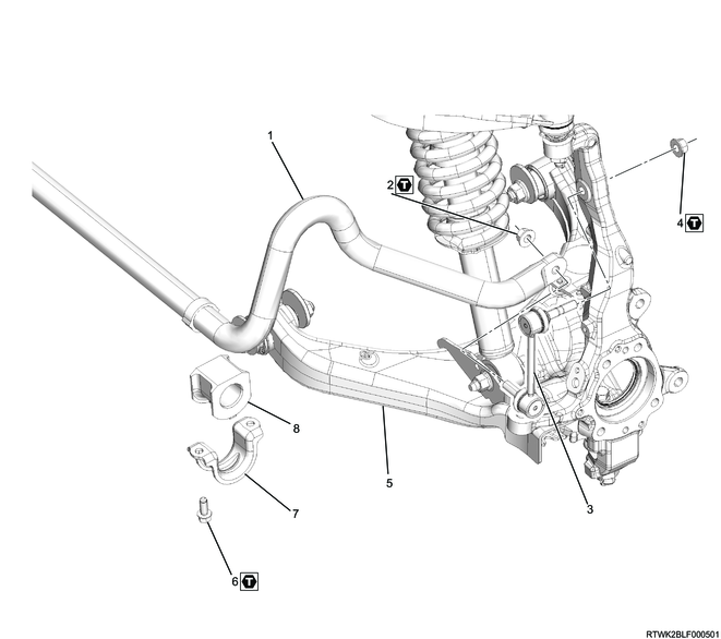
Part name
- Stabilizer bar
- Nut
- Stabilizer link
- Nut
- Lower link
- Bolt
- Clamp
- Rubber bushing
Tightening torque
2: 97.1 N・m { 9.9 kgf・m / 72 lb・ft }
4: 97.1 N・m { 9.9 kgf・m / 72 lb・ft }
6: 47.1 N・m { 4.8 kgf・m / 35 lb・ft }
Upper link (2WD (High ride suspension specification), 4WD)
Part name
- Bushing
- Upper link
- Nut
- Nut
- Upper ball joint
- Nut
- Cotter pin
- Knuckle
- Nut
- Clip
Tightening torque
3: 137 N・m { 14.0 kgf・m / 101 lb・ft }
4: 31.4 N・m { 3.2 kgf・m / 23 lb・ft }
6: 98 N・m { 10.0 kgf・m / 72 lb・ft }
Lower link (2WD (High ride suspension specification), 4WD)
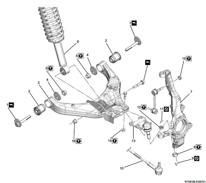
Part name
- Cam bolt
- Bushing
- Lower link
- Cam plate
- Nut
- Shock absorber
- Knuckle
- Nut
- Cotter pin
- Tie rod end
- Cotter pin
- Nut
- Lower ball joint
- Nut
- Nut
- Nut
Tightening torque
5: 186 N・m { 19.0 kgf・m / 137 lb・ft }
8: 147 N・m { 15.0 kgf・m / 108 lb・ft }
12: 98 N・m { 10.0 kgf・m / 72 lb・ft }
14: 126.5 N・m { 12.9 kgf・m / 93 lb・ft }
15: 97.1 N・m { 9.9 kgf・m / 72 lb・ft }
16: 152 N・m { 15.5 kgf・m / 112 lb・ft }
Bumper rubber (2WD (High ride suspension specification), 4WD)
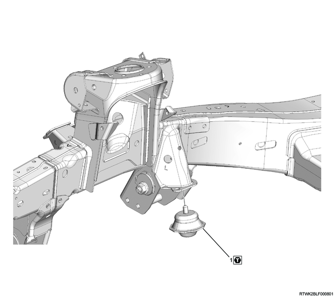
Part name
- Bumper rubber
Tightening torque
1: 106 N・m { 10.8 kgf・m / 78 lb・ft }
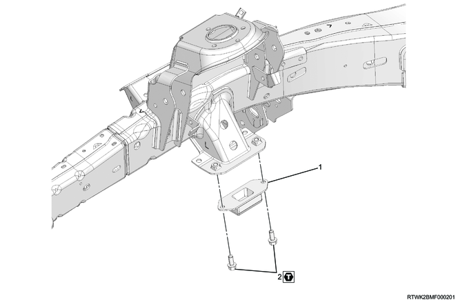
2. Suspension cross member installation
1) Install the suspension cross member to the frame.
Tightening torque: 67 N・m { 6.8 kgf・m / 49 lb・ft } Frame side
Tightening torque: 167 N・m { 17.0 kgf・m / 123 lb・ft } Axle mounting bracket side (4WD)
3. Bumper rubber installation
1) Install the bumper rubber to the bracket.
Tightening torque: 51 N・m { 5.2 kgf・m / 38 lb・ft } 2WD (Except high ride suspension specifications)
Tightening torque: 106 N・m { 10.8 kgf・m / 78 lb・ft } 2WD (High ride suspension specifications), 4WD
4. Lower link installation
1) Apply an oil equivalent to ISO:VG46 to the threaded portion of the bolt.
2) Temporarily tighten the lower link to the frame.
Note
- Temporarily tighten the cam bolt in the position of the alignment mark placed before assembly.
5. Shock absorber installation
1) Connect the shock absorber to the frame.
Note
- Install so that the long stud bolt is in a position outside the vehicle.

Legend
- Long stud bolt
Tightening torque: 55 N・m { 5.6 kgf・m / 41 lb・ft }
2) Apply an oil equivalent to ISO:VG46 to the threaded portion of the bolt.
3) Install the shock absorber to the lower link.
Tightening torque: 152 N・m { 15.5 kgf・m / 112 lb・ft }
6. Upper link installation
1) Apply an oil equivalent to ISO:VG46 to the threaded portion of the bolt.
2) Install the upper link to the frame.
Tightening torque: 137 N・m { 14.0 kgf・m / 101 lb・ft }
3) Connect the brake hose to the upper link.
7. Knuckle installation
1. 2WD (Except high ride suspension specifications)
1) Install the knuckle to the upper ball joint.
Tightening torque: 98 N・m { 10.0 kgf・m / 72 lb・ft }
2) Install the cotter pin to the upper ball joint.
Caution
- Do not reuse the cotter pin.
3) Connect the lower ball joint to the knuckle.
Tightening torque: 147 N・m { 15.0 kgf・m / 108 lb・ft }
4) Install the cotter pin to the lower ball joint.
Caution
- Do not reuse the cotter pin.
5) Referring to the following, adjust the trim height.
Refer to "3.Driveline, Axle 3C.Drive Shaft System wheel alignment check".
2. 2WD (High ride suspension specifications)
1) Install the knuckle to the upper control arm.
Tightening torque: 98 N・m { 10.0 kgf・m / 72 lb・ft }
2) Install the cotter pin upper control arm.
Caution
- Do not reuse the cotter pin.
3) Connect the lower ball joint to the knuckle.
Tightening torque: 147 N・m { 15.0 kgf・m / 108 lb・ft }
4) Install the cotter pin to the lower ball joint.
Caution
- Do not reuse the cotter pin.
5) Referring to the following, adjust the trim height.
Refer to "3.Driveline, Axle 3C.Drive Shaft System wheel alignment check".
3. 4WD
1) Install the knuckle to the upper control arm.
Tightening torque: 98 N・m { 10.0 kgf・m / 72 lb・ft }
2) Install the cotter pin upper control arm.
Caution
- Do not reuse the cotter pin.
3) Connect the lower ball joint to the knuckle.
Tightening torque: 147 N・m { 15.0 kgf・m / 108 lb・ft }
4) Install the cotter pin to the lower ball joint.
Caution
- Do not reuse the cotter pin.
5) Referring to the following, adjust the trim height.
Refer to "3.Driveline, Axle 3C.Drive Shaft System wheel alignment check".
8. Stabilizer bar installation
1. 2WD (Except high ride suspension specifications)
1) Install the clamp and stabilizer bar to the frame.
Tightening torque: 47 N・m { 4.8 kgf・m / 35 lb・ft }
2) Install the stabilizer link to the stabilizer bar and lower link.
Tightening torque: 64 N・m { 6.5 kgf・m / 47 lb・ft }
2. 2WD (High ride suspension specifications), 4WD
1) Install the clamp and stabilizer bar to the frame.
Tightening torque: 47 N・m { 4.8 kgf・m / 35 lb・ft }
2) Install the stabilizer link to the stabilizer bar and knuckle.
Tightening torque: 97 N・m { 9.9 kgf・m / 72 lb・ft }
9. Dust cover installation
1) Install the dust cover to the knuckle.
10. Wheel speed sensor installation
1. Preparations for wheel speed sensor installation
1) Clean the following sections.
- Sensor mounting hole inside and mounting surface of the sensor bracket
- Sensor bracket mounting surface of the knuckle
Note
- Clean foreign material, such as rust and sensor fragments.
- If any rust is found, remove it with a wire brush, etc.
Caution
- If using rust penetrant when removing the wheel speed sensor, clean the part with a parts cleaner, etc.
2. Precautions for wheel speed sensor installation
Caution
- When assembling the hub, do not contact and break the wheel speed sensor body and exciter ring.
- The wheel speed sensor unit contains a magnet so that caution should be taken with metal objects.
- When removing the hub and rotor, or when removing the hub and drum, the wheel speed sensor must be removed first before starting the procedure.
- When the knuckle is removed by hammering etc., remove the wheel speed sensor before starting the work.
- When installing the sensor, use your hand to push the sensor installation flange until it is firmly attached to the installation surface, and then tighten the bolt.
- When inserting the sensor, do not pry or hammer it with a tool.
- Do not tighten the sensor body fixing bolts with an air tool, but temporarily hand tighten and then fully tighten them.
- After tightening the bolts, check that there is no clearance between the mounting flange and the mounting surface again.
- Install the sensor harness using the twist prevention line as a reference to avoid twisting.
- Take care not to pull the harness, which may result in it being cut.
- Confirm that there is no harness interference.
- Be careful not to damage the wheel speed sensor.
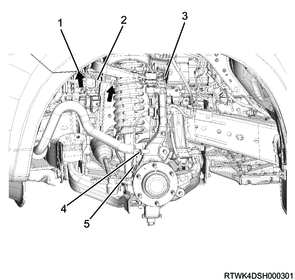
3. Installation (ABS-specification 2WD (Except high ride suspension specifications))
1) Install the wheel speed sensor to the knuckle.
Tightening torque: 8.2 N・m { 0.8 kgf・m / 73 lb・in }
2) Install the harness bracket to the upper link and knuckle.
Tightening torque: 8.2 N・m { 0.8 kgf・m / 73 lb・in } Harness bracket tightening bolt
Tightening torque: 8.2 N・m { 0.8 kgf・m / 73 lb・in } Harness bracket tightening nut
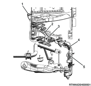
Legend
- Connector position
- Wheel speed sensor
- Harness bracket tightening nut
- Harness bracket tightening bolt
- Wheel speed sensor tightening bolt
3) Connect the harness connector to the wheel speed sensor.
4) Make sure that the harness is not twisted.
4. Installation (ABS-specification 2WD (High ride suspension specifications), ABS-specification 4WD)
1) Install the wheel speed sensor to the knuckle.
Tightening torque: 8.2 N・m { 0.8 kgf・m / 73 lb・in }
2) Install the harness bracket to the upper link and knuckle.
Tightening torque: 8.2 N・m { 0.8 kgf・m / 73 lb・in } Harness bracket tightening bolt
Tightening torque: 8.2 N・m { 0.8 kgf・m / 73 lb・in } Harness bracket tightening nut
3) Connect the harness clips to the harness as indicated by the arrows in the following diagram.
Legend
- Connector position
- Wheel speed sensor
- Harness bracket tightening nut
- Harness bracket tightening bolt
- Wheel speed sensor tightening bolt
4) Connect the harness connector to the wheel speed sensor.
5) Make sure that the harness is not twisted.
5. Inspection after vehicle restoration
1) Turn ON the ignition switch, and check whether the ABS warning light turns OFF after illuminating for approximately 3 seconds.
2) Start the engine and drive the vehicle straight forward from a stationary state. Slowly accelerate to 15 km/h {9.3 mph} and then slowly apply the brake until the vehicle stops. Check that there are no abnormal noises or problems with the braking force during this procedure.
3) Confirm whether the following symptom occurs during verification actions above.
- The ABS warning light illuminates, or does not illuminate.
- ABS operation noise or motor rotation noise is caused.
- Brake pedal kickbacks are felt.
- Desired braking force is not reached.
4) When the above symptom occurs, take the following action.
- Check the installation status of the wheel speed sensor and connection status of the connector.
- Check the DTCs, and perform inspection and take remedies for the ABS system in accordance with the diagnostic procedure for each DTC.
Caution
- Since the ABS rotates the motor for a moment right immediately after the vehicle is started, sound of rotating motor may be heard. This operation for initial confirmation task and not at fault.
11. Power steering unit connect
1) Connect the tie rod end to the knuckle.
2) Install the castle nut to the ball joint.
Tightening torque: 98 N・m { 10.0 kgf・m / 72 lb・ft }
3) Install the cotter pin to the ball joint.
Caution
- Do not reuse the cotter pin.
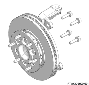
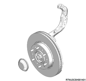
12. Front hub installation
1. 2WD (Except high ride suspension specifications)
1) Install the knuckle cap to the knuckle.
2) Install the front hub and brake rotor to the knuckle.
3) Install the bolt to the knuckle.
Tightening torque: 85 N・m { 8.7 kgf・m / 63 lb・ft }
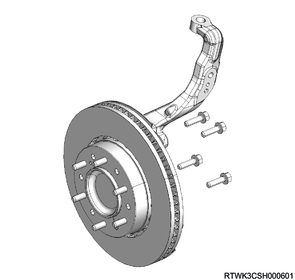
2. 2WD (High ride suspension specifications)
1) Install the knuckle cap to the knuckle.
2) Install the front hub and brake rotor to the knuckle.
3) Install the bolt to the knuckle.
Tightening torque: 85 N・m { 8.7 kgf・m / 63 lb・ft }
3. 4WD
1) Install the front hub and brake rotor to the knuckle.
2) Install the bolt to the knuckle.
Tightening torque: 85 N・m { 8.7 kgf・m / 63 lb・ft }
3) Install the washer and lock nut to the front hub.
Tightening torque: 127 N・m { 13.0 kgf・m / 94 lb・ft }
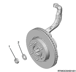
Legend
- Lock nut
- Washer
4) Install the cotter pin to the front hub.
Caution
- If the cotter pin hole position does not align, rotate the lock nut in the tightening direction to align it.
5) Install the hub cap to the front hub.
13. Brake caliper installation
1) Install the brake support to the knuckle.
Tightening torque: 205 to 245 N・m { 20.9 to 25.0 kgf・m / 151 to 181 lb・ft }
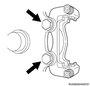
2) Install the disc brake pad and shim to the brake support.
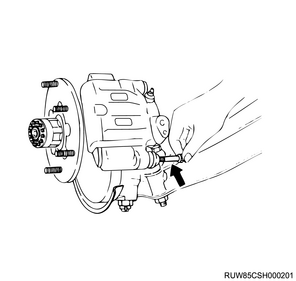
3) Install the brake caliper to the brake support.
4) Install the lock bolt to the brake caliper.
Tightening torque: 32 to 42 N・m { 3.3 to 4.3 kgf・m / 24 to 31 lb・ft }
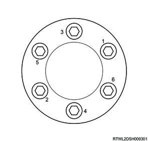
14. Disc wheel installation
1. Models with aluminum wheels
1) Temporarily tighten the disc wheel to the vehicle.
2) Lower vehicle.
3) Final tighten the wheel nut in the order shown in the diagram.
Tightening torque: 120 N⋅m {12 kgf⋅m / 87 lb⋅ft}
Caution
- After completing installation, make sure to further tighten the wheel nuts to the specified torque after the vehicle has been driven a distance exceeding the standard value.
Standard: 50 to 100 km { 31 to 62 mile }
4) Install the wheel cap to the disc wheel.
Note
- For models with 18-inch aluminum wheels, align the wheel cap groove with the air valve before installing.
5) Check that the surfaces of the wheel cap and wheel are flat.
Note
- If the surfaces are not flat, the wheel cap may fall off.
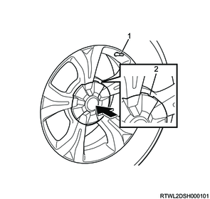
Legend
- Valve
- Wheel cap groove
2. Models with steel wheels
1) Temporarily tighten the disc wheel and wheel cap to the vehicle.
2) Lower vehicle.
3) Final tighten the wheel nut in the order shown in the diagram.
Tightening torque: 120 N⋅m {12 kgf⋅m / 87 lb⋅ft}
Caution
- After completing installation, make sure to further tighten the wheel nuts to the specified torque after the vehicle has been driven a distance exceeding the standard value.
Standard: 50 to 100 km { 31 to 62 mile }
15. Wheel alignment check
16. Preliminary and post procedures
1. Post procedures
1) Connect the battery cable to the battery negative terminal.
2) Referring to the following, perform the setting of the front door power window switch with AUTO UP/AUTO DOWN function.
3) Close the engine hood.