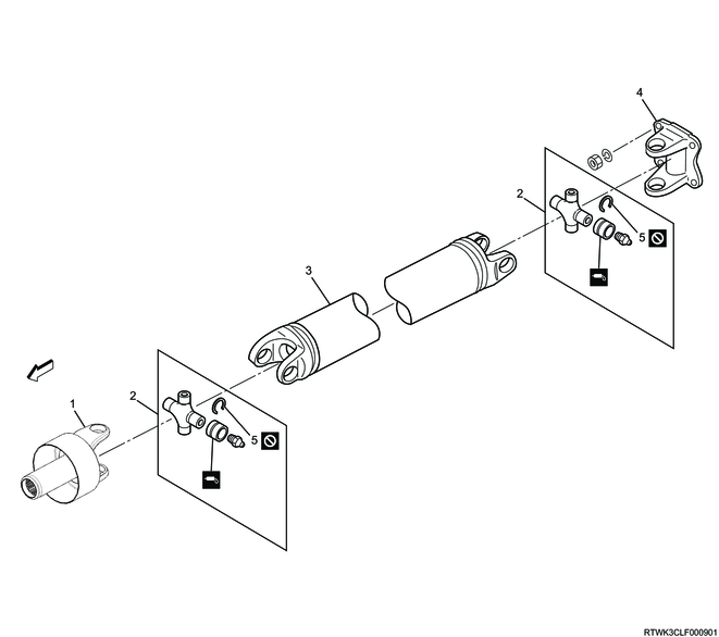
1. Component views
Rear propeller shaft (Two-piece type)

Part name
- Spline yoke
- journal assembly
- 1st tube assembly
- Center bearing
- Plain washer
- center yoke
- Lock nut
- 2nd tube assembly
- Flange yoke
- Snap ring
Rear propeller shaft (One-piece type)
Part name
- Spline yoke
- journal assembly
- Tube assembly
- Flange yoke
- Snap ring
2. Rear propeller shaft disassembly
1. Two-piece type
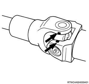
1) Place alignment marks on the following part connections.
- Spline yoke
- 1st tube assembly
- center yoke
- 2nd tube assembly
- Flange yoke
Caution
- Because the propeller shaft is adjusted to have a precise balance, always place alignment marks on each of the joints before removing or disassembling.
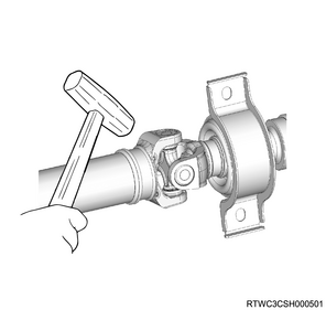
2) Remove the snap ring from the following parts.
- Spline yoke
- 1st tube assembly
- center yoke
- 2nd tube assembly
- Flange yoke
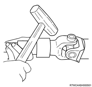
3) Lightly tap the yoke shoulder with a copper or wooden hammer, etc., and remove the needle roller bearing from the following parts.
- Spline yoke
- center yoke
- Flange yoke
4) Remove the spline yoke from the 1st tube assembly.
5) Remove the center yoke and flange yoke from the 2nd tube assembly.
6) Lightly tap the yoke shoulder with a copper or wooden hammer, etc., and remove the needle roller bearing from the 1st and 2nd tube assemblies.
7) Remove the spider from the 1st and 2nd tube assemblies.
8) Remove the center yoke and 1st tube assembly from the center bearing.
Caution
- Do not reuse the lock nuts.
9) Remove the plain washer from the center yoke.
10) Remove the grease fitting from the needle roller bearing.
2. One-piece type
1) Place alignment marks on the following part connections in the same manner as two-piece type.
- Spline yoke
- Tube assembly
- Flange yoke
Caution
- Because the propeller shaft is adjusted to have a precise balance, always place alignment marks on each of the joints before removing or disassembling.
2) Remove the snap ring from the following parts.
- Spline yoke
- Tube assembly
- Flange yoke
3) Lightly tap the yoke shoulder with a copper or wooden hammer, etc., and remove the needle roller bearing from the spline yoke and flange yoke.
4) Remove the spline yoke and flange yoke from the tube assembly.
5) Lightly tap the yoke shoulder with a copper or wooden hammer, etc., and remove the needle roller bearing from the tube assembly.
6) Remove the spider from the tube assembly.
7) Remove the grease fitting from the needle roller bearing.