1. Component views
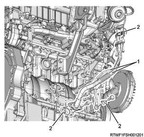
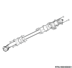
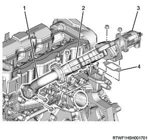
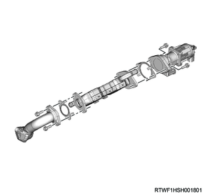
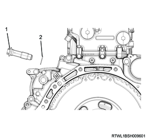
Flywheel housing
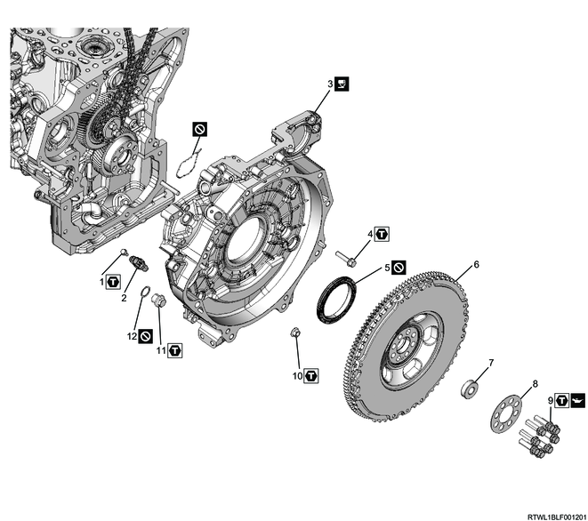
Part name
- Bolt
- CKP sensor
- Flywheel housing
- Bolt
- Crankshaft rear oil seal
- Flywheel
- Bearing
- Washer
- Bolt
- Nut
- Plug
- O-ring
Tightening torque
1: 5.0 N・m { 0.51 kgf・m / 44.3 lb・in }
4: 52 N・m { 5.3 kgf・m / 38 lb・ft }
9-1: 40 N・m { 4.1 kgf・m / 30 lb・ft }
9-2: 60 to 90 °
10: 52 N・m { 5.3 kgf・m / 38 lb・ft }
11: 63 N・m { 6.4 kgf・m / 46 lb・ft }
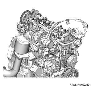
2. Engine removal
Refer to "1.Engine 1B.Mechanical(RZ4E-TC) engine removal".
3. Cylinder head cover removal
4. Engine oil drain
1) Remove the drain plug from the oil pan, and drain the engine oil to a pan.
2) Install the drain plug to the oil pan.
Caution
- Do not reuse the gasket.
- Wipe off any oil attached to the drain plug hole.
- Do not forget to tighten the drain plug.
Tightening torque: 83 N・m { 8.5 kgf・m / 61 lb・ft }
5. Vacuum hose removal
1) Disconnect the vacuum hose from the turbocharger control solenoid valve.
2) Remove the vacuum hose from the turbocharger and vacuum pipe.
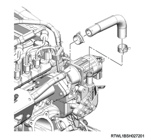
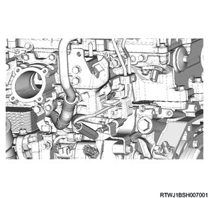
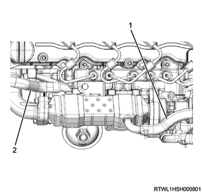
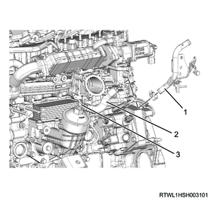
6. Turbocharger water hose disconnect
1) Disconnect the turbocharger water feed hose from the water feed pipe and return pipe.
2) Disconnect the turbocharger water return hose from the water feed pipe and return pipe.
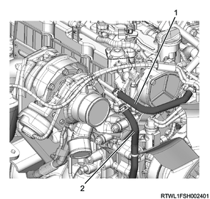
Legend
- Turbocharger water feed hose
- Turbocharger water return hose
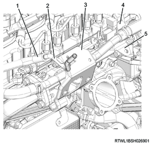
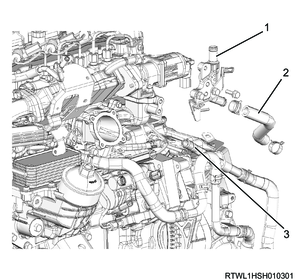
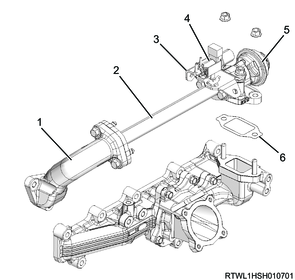
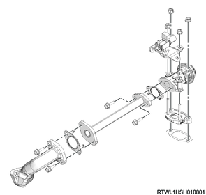
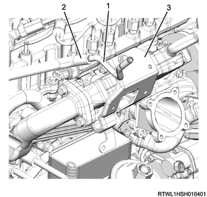
7. Turbocharger oil pipe removal
1) Remove the turbocharger oil pipe and gasket from the turbocharger and cylinder block.
Caution
- To prevent the intrusion of foreign material, seal the connections.
- Do not reuse the gasket.
Legend
- Turbocharger oil pipe
- Gasket
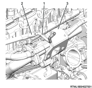
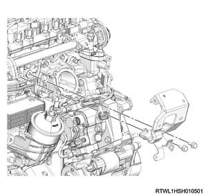
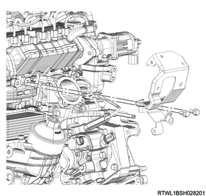
8. Turbocharger bracket removal
1) Remove the turbocharger bracket from the turbocharger and cylinder block.
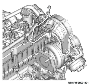
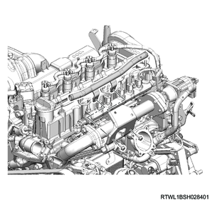
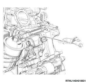
9. Turbocharger heat protector removal
1) Remove the turbocharger heat protector from the turbocharger.
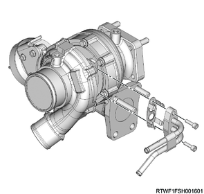
10. Turbocharger removal
1) Remove the turbocharger and gasket from the exhaust manifold.
Caution
- To prevent the intrusion of foreign material, seal the connections.
- Do not reuse the gasket.
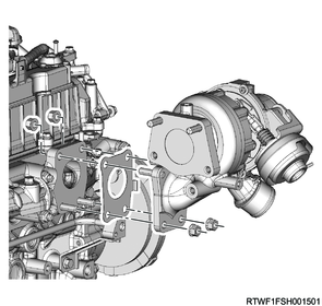
2) Remove the water feed and return pipe, as well as the gasket from the turbocharger.
Caution
- Do not reuse the gasket.
11. Exhaust manifold removal
1) Remove the heat protector from the exhaust manifold.
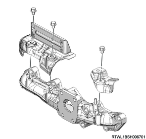
2) Remove the exhaust manifold and gasket from the cylinder head.
Caution
- Do not reuse the gasket.

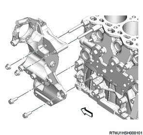
12. Generator bracket removal
1) Remove the generator bracket from the cylinder block.
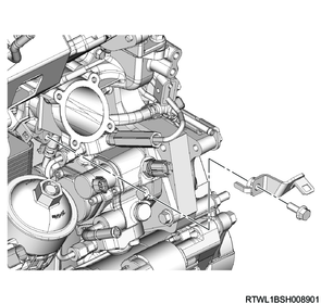
13. Intake throttle valve removal
1) Disconnect the connector from the intake throttle valve.
2) Remove the intake throttle valve and gasket from the inlet manifold.
Caution
- Do not reuse the gasket.
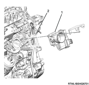
Legend
- Intake throttle valve
- Gasket
14. Water pipe removal
1. Except for Euro4 specifications
1) Disconnect the vacuum hose from the vacuum pipe.
2) Remove the vacuum pipe from the air duct bracket.
Euro2 specifications
Legend
- Vacuum pipe
- Vacuum hose
- Bracket
Except for Euro2 specifications
Legend
- Vacuum hose
- Vacuum pipe
- Bracket
- Relief valve control solenoid valve
- Relief valve control solenoid valve bracket
3) Remove the water hose from the water pipe.
Manual transmission models

Automatic transmission models
4) Remove the water pipe from the air duct bracket.
5) Remove the pipe clip from the water pipe.
6) Remove the water pipe from the inlet cover.
Manual transmission models
Automatic transmission models
15. EGR cooler water hose disconnect
1. Euro4 specifications
1) Disconnect the EGR cooler water feed hose from the EGR cooler.
2) Disconnect the EGR cooler water return hose from the EGR cooler.
Manual transmission models
Legend
- EGR cooler water return hose
- EGR cooler water feed hose
Automatic transmission models
Legend
- EGR cooler water return hose
- EGR cooler water feed hose
3) Disconnect the EGR cooler water hose from EGR cooler water pipe A.
4) Remove EGR cooler water pipe A from the inlet cover.
Manual transmission models
Legend
- EGR cooler water pipe A
- EGR cooler water hose
- EGR cooler water pipe B
Automatic transmission models
Legend
- EGR cooler water pipe A
- EGR cooler water hose
- Water pipe
16. Glow plug removal
1) Remove the glow plug terminal and glow plug connector from the glow plug.
Legend
- Glow plug terminal
- Glow plug connector
2) Remove the glow plug from the cylinder head.
17. Relief valve removal
1. Except for Euro2 and Euro4 specifications
1) Remove the air duct bracket from the inlet cover.
2) Remove the harness bracket from the inlet cover.
3) Remove the following parts as a set from the cylinder head and inlet cover.
- EGR pipe
- EGR duct
- Relief valve
- Gasket
- Relief valve control solenoid valve
Caution
- Do not reuse the gasket.
Legend
- EGR duct
- EGR pipe
- Relief valve control solenoid valve bracket
- Relief valve control solenoid valve
- Relief valve
- Gasket
Caution
- Do not reuse the gasket.
- Seal to prevent foreign material from entering.
18. EGR removal
1. Euro2 specifications
1) Remove the air duct bracket from the inlet cover.
2) Remove the harness bracket from the inlet cover.
3) Remove the following parts as a set from the cylinder head and inlet cover.
- EGR pipe
- EGR valve
- EGR duct
- Gasket
Legend
- EGR duct
- EGR pipe
- EGR valve
- Gasket
4) Remove the following parts from the EGR pipe.
- EGR valve
- EGR duct
- Gasket
Caution
- Do not reuse the gasket.
- Seal to prevent foreign material from entering.
2. Euro4 specifications
1) Disconnect the vacuum hose from the vacuum pipe.
2) Remove the vacuum pipe from the bracket.
Legend
- Vacuum pipe
- Vacuum hose
- Bracket
3) Remove the air duct bracket from the inlet cover.
4) Remove the harness bracket from the inlet cover.
5) Remove the following parts as a set from the cylinder head and inlet cover.
- EGR cooler
- EGR valve
- EGR duct
- Gasket
Caution
- Do not reuse the gasket.
Legend
- EGR duct
- EGR cooler
- EGR valve
- Gasket
6) Remove the following parts from the EGR cooler.
- EGR valve
- EGR duct
- Gasket
Caution
- Do not reuse the gasket.
- Seal to prevent foreign material from entering.
19. Inlet cover removal
1) Remove the inlet cover from the cylinder head.
Caution
- Do not reuse the gasket.
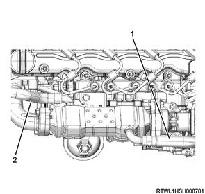
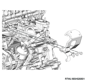
20. Fuel leak-off pipe removal
1) Disconnect the fuel leak-off hose from the fuel leak-off pipe.
2) Remove the fuel leak-off pipe from the common rail (fuel rail) and flywheel housing.
Caution
- Cover the exposed section to prevent the intrusion of foreign material.

Legend
- Fuel leak-off pipe
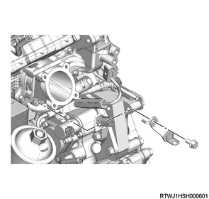
21. Fuel feed pipe removal
1) Remove the clip from the fuel feed pipe.
2) Remove the fuel feed pipe from the fuel supply pump and common rail (fuel rail).
Caution
- Do not reuse the fuel feed pipe.
- Cover the exposed section to prevent the intrusion of foreign material.

Legend
- Fuel feed pipe
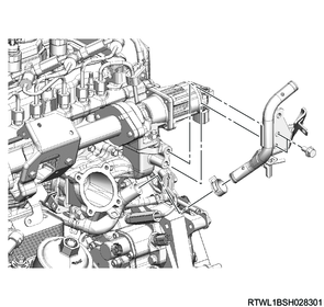
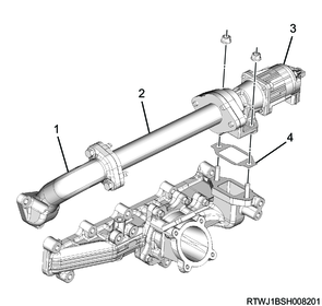
22. Water pipe removal
1. Automatic transmission models
1) Disconnect the EGR cooler water hose from EGR cooler water pipe B.
2) Remove the water pipe and EGR cooler water hose as a set from the flywheel housing.

Legend
- EGR cooler water pipe B
- Nut
- Water pipe
- EGR cooler water hose
23. Common rail (fuel rail) removal
1) Remove the bracket from the cylinder head.
2) Disconnect the connector from the FRP sensor.
3) Remove the common rail (fuel rail) from the cylinder head.
Caution
- Do not hold the FRP sensor.
- Take care not to damage the connector section of the FRP sensor.

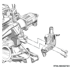
24. Turbocharger control solenoid valve removal
1) Disconnect the vacuum hose from the turbocharger control solenoid valve.
2) Remove the connector from the turbocharger control solenoid valve.
3) Remove the turbocharger control solenoid valve from the bracket.
4) Remove the bracket from the cylinder head.
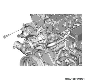
25. Thermostat housing removal
1) Disconnect the connector from the engine coolant temperature sensor.
2) Remove the thermostat housing from the cylinder head and front cover.
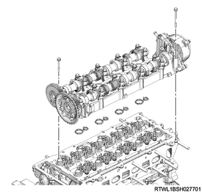
26. Camshaft carrier removal
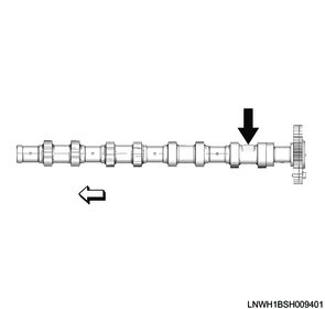
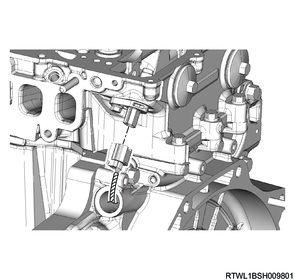
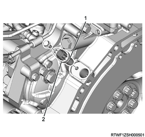
1) Remove the cam angle sensor rotor from the inlet camshaft.
Note
- Referring to the diagram, secure the section indicated by the arrow.
Fixing position
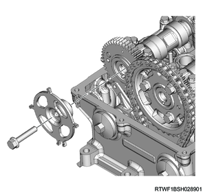
2) Remove the timing chain tensioner and gasket from the flywheel housing.
Caution
- Do not reuse the gasket.
Legend
- Timing chain tensioner
- Gasket
3) Remove the timing chain from the camshaft sprocket.
4) Disconnect the vacuum hose from the vacuum pump.
5) Remove the camshaft carrier and gasket from the cylinder head.
Caution
- Do not reuse the gasket.
6) Remove the dowel pin from the cylinder head.
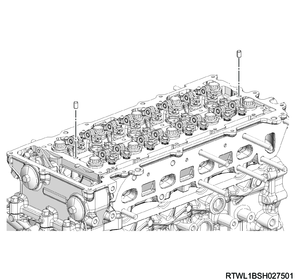
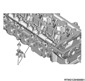
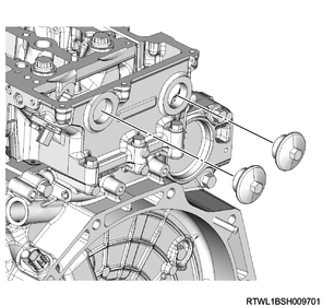
27. Cylinder head removal
1) Disconnect the connector from the CMP sensor.
2) Remove the plug from the cylinder head.
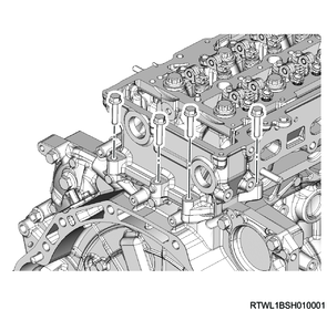
3) Remove the following parts from the cylinder head.
- Timing chain tension lever
- Timing chain guide bolt
- Timing chain lever pivot

Legend
- Timing chain tension lever
- Timing chain guide bolt
- Timing chain lever pivot
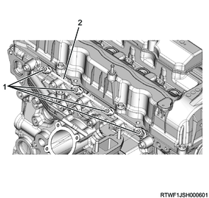
4) Remove the cylinder head outside bolts from the cylinder head.
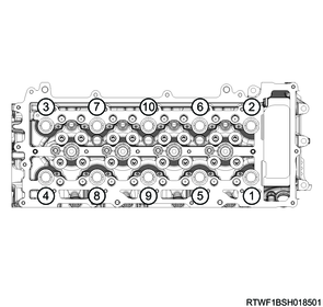
5) Loosen the cylinder head bolts in the order shown in the diagram.
Caution
- Do not reuse the cylinder head bolts.
6) Remove the cylinder head gasket from the cylinder head.
Caution
- Do not reuse the cylinder head gasket.
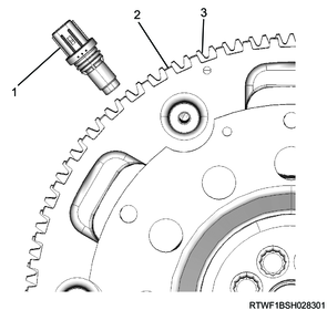
28. CKP sensor removal
1) Disconnect the connector from the CKP sensor.
2) Remove the CKP sensor from the flywheel housing.
Legend
- O-ring
- CKP sensor
29. Flywheel removal
1. Manual transmission models
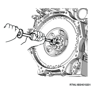
1) Remove the pilot bearing from the flywheel using the special tool.
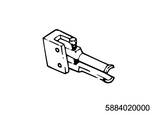
SST: 5-8840-2000-0 - Pilot bearing remover
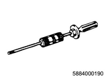
SST: 5-8840-0019-0 - Sliding hammer
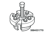
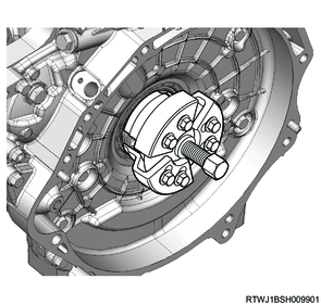
2) Install the special tool to the starter motor installation section of the flywheel housing.
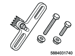
SST: 5-8840-3174-0 - crankshaft stopper
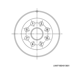
3) Gradually loosen the flywheel mounting bolts in the order shown in the diagram, and remove the washer and flywheel from the crankshaft.
Note
- After loosening all of the bolts, remove the special tool.
Caution
- Do not damage the flywheel sensor rotor section.
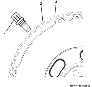
Legend
- CKP sensor
- Sensor rotor section
- Ring gear
2. Automatic transmission models
1) Install the special tool to the starter motor installation section of the flywheel housing.
SST: 5-8840-3174-0 - crankshaft stopper
2) Gradually loosen the flywheel mounting bolts in the order shown in the diagram, and remove the following parts from the crankshaft.
- Washer
- Flexible plate
- Flywheel
Note
- After loosening all of the bolts, remove the special tool.
Caution
- Do not damage the flywheel sensor rotor section.
Legend
- CKP sensor
- Sensor rotor section
- Ring gear
30. Crankshaft rear oil seal removal
1) Remove the crankshaft rear oil seal and slinger from the crankshaft using the special tool.
Caution
- Do not reuse the crankshaft rear oil seal.
- Do not damage the oil seal installation surface of the crankshaft and flywheel housing.
SST: 5-8840-3177-0 - slinger puller
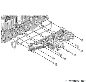
31. Flywheel housing removal
1) Remove the flywheel housing from the cylinder block.
Caution
- Do not reuse the gasket.
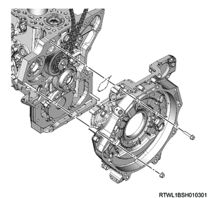
2) Remove the timing chain from the idle gear A sprocket.