1. SRS control overview
Deploying from the top center part of the steering column and the passenger side top part of the instrument panel, the driver airbag and passenger airbag support the protection provided by the seat belts. The seat belt is equipped with a pretensioner. The SRS airbag deploys when the impact of a frontal collision greater than a certain amount occurs. For models with knee airbags, the knee airbag under the driver-side instrument panel is also deployed. The SRS deployment signal is sent to the BCM to unlock all the doors.
For models with side airbags and curtain airbags, in addition to the above system, the side airbag and curtain airbag deploy when the impact of a side collision greater than a certain amount occurs. For models with far side airbags, the far side airbag is deployed. When the SRS control unit detects a malfunction in the SRS system, it illuminates the SRS airbag warning light in the instrument panel cluster.
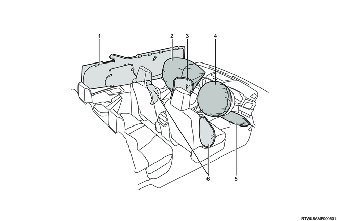
Legend
- Deployed curtain airbag
- Deployed passenger airbag
- Deployed far side airbag
- Deployed driver airbag
- Deployed knee airbag
- Deployed side airbag
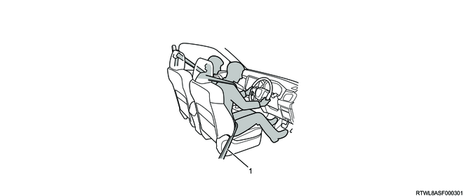
Legend
- Seat belt with pretensioner
This system consists of an SRS control unit, SRS airbag, SRS coil, seat belt with pretensioner, front airbag sensor, specialized wire harness, and SRS airbag warning light in the instrument panel cluster, and forms the deployment circuit. Also, a G sensor is built into the SRS control unit. The G sensor and front airbag sensor convert impacts into electrical signals, and when the electrical signals exceed a certain value, the SRS control unit sends a current to the driver airbag, passenger airbag, and pretensioner, and the driver airbag, passenger airbag, and seat belt with pretensioner are deployed. For models with knee airbags, the driver knee airbag is also deployed. Models with side airbags and curtain airbags, in addition to the above system, are equipped with a side airbag, curtain airbag, door side airbag sensor, floor side airbag sensor, and rear side airbag sensor that provide safety in side collisions. In the event of a side collision, if the electrical signals exceed a certain value, the SRS control unit sends a current to the side airbag and curtain airbag, and the collision side curtain airbag, side airbag, and seat belt with pretensioner are deployed. For models with far side airbags, the far side airbag is also deployed.
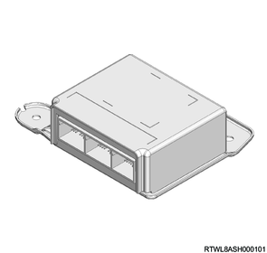
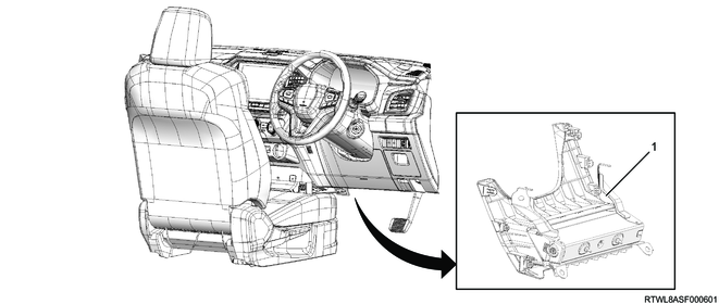
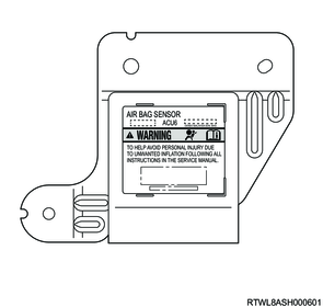
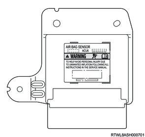
2. SRS control unit
Warning
- During the maintenance work, do not hit or shake the SRS control unit when handling it.
Except models with side airbags and curtain airbags

Models with side airbags and curtain airbags
The SRS control unit has the following functions.
1) Energy backup
The SRS control unit stores the energy required for activating the airbag and seat belt with pretensioner when the ignition voltage is lost due to a frontal collision.
2) Collision detection
The SRS control unit monitors impacts and detects frontal collisions that require deployment of the SRS airbag and the seat belt with pretensioner.
3) Deployment of SRS airbag and seat belt with pretensioner
If the impact of a frontal collision greater than a certain amount is detected, in order to deploy the SRS airbag and the seat belt with pretensioner, the SRS control unit sends the required current to the SRS airbag and the seat belt with pretensioner.
4) Malfunction detection
The SRS control unit performs the system diagnosis, and a DTC is set if a malfunction is detected.
5) Malfunction diagnosis
The SRS control unit can display the recorded DTCs and the system operation status on the scan tool.
6) Warning to drivers
The SRS control unit warns the driver of a malfunction in the system by illuminating the SRS airbag warning light.
7) Passenger airbag deployment inhibition
When the driver turns OFF the passenger side SRS airbag cut off switch, the SRS control unit inhibits the deployment of the passenger airbag and passenger side airbag, and it illuminates the passenger side SRS airbag OFF indicator light.
Note
- The harness connector for connecting the SRS control unit and SRS harness uses a shorting clip for the contact surface of specific terminals.
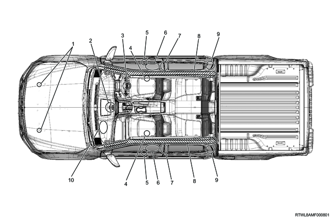
Except models with side airbags and curtain airbags
Note
- The illustration shows regular cab RHD models.
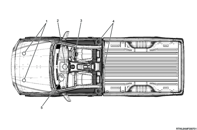
Legend
- Front airbag sensor
- SRS control unit
- Driver airbag
- Seat belt with pretensioner
- Passenger airbag
Models with side airbags and curtain airbags
Note
- The illustration shows an RHD model.
Models without far side airbags and knee airbags
Legend
- Front airbag sensor
- SRS control unit
- Driver airbag
- Floor side airbag sensor
- Door side airbag sensor
- Side airbag
- Seat belt with pretensioner
- Curtain airbag
- Rear side airbag sensor
- Passenger side SRS airbag cut off switch
- Passenger airbag
Models with far side airbags and knee airbags
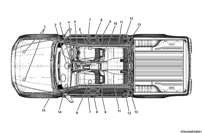
Legend
- Front airbag sensor
- SRS control unit
- Passenger side SRS airbag indicator
- Driver airbag
- Driver knee airbag
- Floor side airbag sensor
- Door side airbag sensor
- Side airbag
- Seat belt with front pretensioner
- Far side airbag
- Curtain airbag
- Rear side airbag sensor
- Seat belt with rear pretensioner
- Passenger side SRS airbag cut off switch
- Passenger airbag
3. SRS controls components
1. SRS airbag warning light
The SRS airbag warning light informs the driver of malfunctions in the system. If no malfunction is detected with the ignition switch ON, the SRS airbag warning light turns OFF after illuminating for 6 seconds.
2. Passenger side SRS airbag indicator
The passenger side SRS airbag indicator is installed to the center console. The passenger side SRS airbag indicator informs the driver of the deployment permission and deployment inhibition states of the passenger airbag and passenger side airbag. When the power mode (models with passive entry and start system) or ignition switch (except models with passive entry and start system) is turned ON, the passenger side SRS airbag OFF indicator light and passenger side SRS airbag ON indicator light in the passenger side SRS airbag indicator turn OFF after illuminating for 4 seconds.
When the passenger side SRS airbag cut off switch is turned ON with the power mode (models with passive entry and start system) or ignition switch (except models with passive entry and start system) ON, the passenger side SRS airbag ON indicator light illuminates. When the passenger side SRS airbag cut off switch is turned OFF, the passenger side SRS airbag OFF indicator light illuminates.
Regardless of whether the passenger side SRS airbag cut off switch is ON or OFF, when the SRS control unit detects a malfunction in the passenger side SRS airbag cut off switch, it illuminates the passenger side SRS airbag ON indicator light.
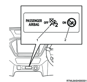
Legend
- Passenger side SRS airbag OFF indicator light
- Passenger side SRS airbag ON indicator light
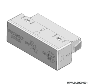
3. Passenger side SRS airbag cut off switch
The passenger side SRS airbag cut off switch is installed in the glove box, and it is used for switching the passenger air bag and passenger side airbag between deployment permission and deployment inhibition. The passenger side SRS airbag cut off switch is operated by inserting the key. In accordance with the passenger side SRS airbag cut off switch operation, the SRS control unit illuminates the passenger side SRS airbag OFF indicator light or passenger side SRS airbag ON indicator light.
When the passenger side SRS airbag cut off switch is turned ON with the power mode (models with passive entry and start system) or ignition switch (except models with passive entry and start system) ON, deployment of the passenger airbag and passenger side airbag is permitted. When the passenger side SRS airbag cut off switch is turned OFF, deployment of the passenger airbag and passenger side airbag is inhibited.
Regardless of whether the passenger side SRS airbag cut off switch is ON or OFF, when the SRS control unit detects a malfunction in the passenger side SRS airbag cut off switch, it illuminates the passenger side SRS airbag ON indicator light and permits the passenger airbag and passenger side airbag to deploy.
| Passenger side SRS airbag cut off switch |
Passenger airbag and passenger side airbag |
Passenger side SRS airbag ON indicator light |
Passenger side SRS airbag OFF indicator light |
| ON |
Deploy |
ON |
OFF |
| OFF |
Do not deploy |
OFF |
ON |
| Failure |
Deploy |
ON |
OFF |
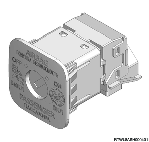

Legend
- Passenger side SRS airbag cut off switch
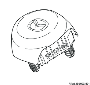
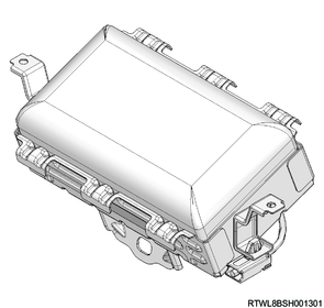
4. SRS airbag
The SRS airbag consists of the airbag and the inflator (a gas-generating agent and igniter). The SRS control unit sends a current to the deployment circuit when a frontal collision with an impact greater than a certain level occurs. The current flowing in the inflator ignites the gas-generating agent in the airbag. The gas generated from this reaction rapidly expands the airbag. The SRS control unit harness connector is equipped with a shorting clip. When the SRS control unit harness connector is disconnected, the shorting clip shorts the airbag (High) circuit and (Low) circuit together. Shorting the circuits prevents unnecessary deployment of the airbag when performing maintenance of the SRS airbag, steering column, or other system parts.
Driver airbag
Passenger airbag
5. SRS airbag (Models with side airbag and curtain airbag)
In addition to the above function, the system also provides safety in side collisions for models with side airbags and curtain airbags. The SRS control unit sends a current to the deployment circuit when the impact of a side collision greater than a certain amount occurs. The current flowing in the inflator ignites the gas-generating agent in the airbag. The gas generated from this reaction rapidly expands the airbag.
Side airbag
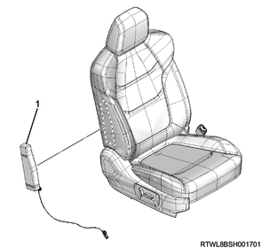
Legend
- Side airbag
Curtain airbag
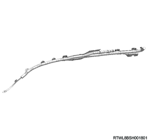
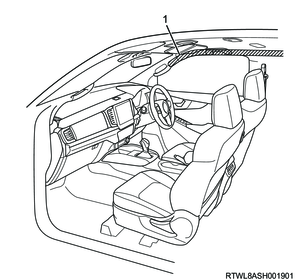
Legend
- Curtain airbag
6. SRS airbag (Models with far side airbags and knee airbag)
In addition to the above system, the far side airbag and knee airbag protect the driver's legs and passenger side of the driver upper body. The SRS control unit sends a current to the deployment circuit when a collision with an impact greater than a certain level occurs. The current flowing in the inflator ignites the gas-generating agent in the airbag. The gas generated from this reaction rapidly expands the airbag.
Far side airbag
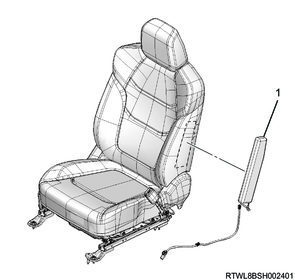
Legend
- Far side airbag
Driver knee airbag
Legend
- Driver knee airbag
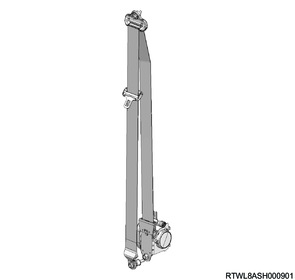
7. Seat belt with pretensioner
The seat belt with pretensioner consists of the seat belt and the gas generator section. The SRS control unit sends a current to the deployment circuit when a frontal collision with an impact greater than a certain level occurs. The gas generator section of the seat belt with pretensioner is then ignited. Gas generated by this ignition retracts loose areas of the seat belt and firmly restrains the driver's upper body.
8. SRS coil
The SRS coil is installed to the steering column. It allows the steering wheel to rotate while maintaining continuous continuity of the deployment circuit and the SRS airbag. The shorting clip is installed to the yellow 2-pin connector located near the bottom of the steering column. When the yellow 2-pin connector is removed, the shorting clip shorts the airbag (High) circuit and (Low) circuit together. Shorting the circuits prevents unnecessary deployment of the airbag when performing maintenance of the SRS airbag, steering column, or other system parts.
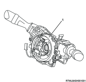
Legend
- SRS coil
Caution
- As the SRS coil is integrated with the combination switch, it cannot be replaced separately.
When replacing the SRS coil, replace as a set with the combination switch. - Because the combination switch is integrated with the SRS coil and steering angle sensor, do not remove it from the combination switch or rotate it.
Note
- The steering angle sensor is only equipped to models with ESC.
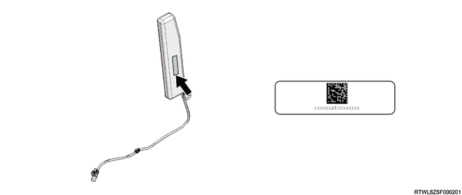
9. Front airbag sensor
The front airbag sensors are installed to the inside of the front bumper. They are installed to the left and right at the position shown in the illustration. They detect a frontal collision of the vehicle and send a signal to the SRS control unit.
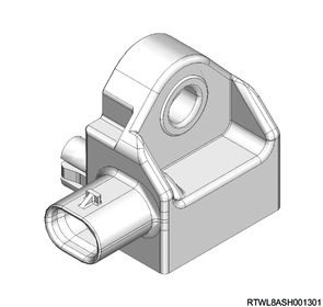
Front airbag sensor installation position
Legend
- Front airbag sensor
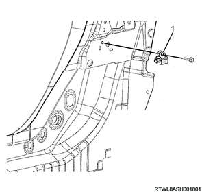
10. Door side airbag sensor
Door side airbag sensors are installed to the front door. They are installed to the left and right at the position shown in the illustration. They detect a side collision near the door and send signals to the SRS control unit.

Door side airbag sensor installation position

Legend
- Door side airbag sensor
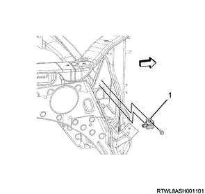
11. Floor side airbag sensor
Floor side airbag sensors are installed to the area near the center pillar trim on the floor. They are installed to the position shown in the illustration, as one is installed to the left and the other is installed to the right. They detect vehicle side collisions and send signals to the SRS control unit.
Floor side airbag sensor installation position
Legend
- Floor side airbag sensor
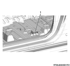
12. Rear side airbag sensor
The rear side airbag sensors are installed to the inner side of the rear pillar trim. They are installed to the position shown in the illustration, as one is installed to the left and the other is installed to the right. They detect vehicle side collisions and send signals to the SRS control unit.
Rear side airbag sensor installation position
Legend
- Rear side airbag sensor
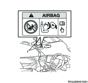
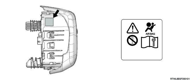
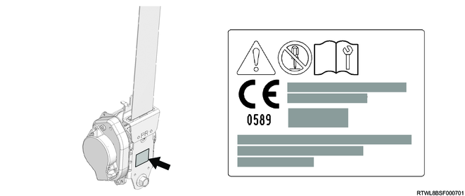
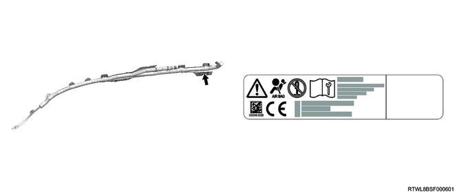
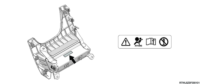
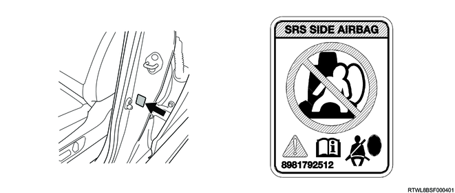
13. Caution label
A caution label describing the special precautions for the SRS airbag and the seat belt with pretensioner equipped to the vehicle is attached.
Rear side of the sun visor on the passenger side
Driver airbag back side
Passenger airbag back side

Seat belt with pretensioner
Side airbag

Curtain airbag
Knee airbag
Far side airbag
SRS control unit
Except models with side airbags and curtain airbags
Models with side airbags and curtain airbags
Driver door side
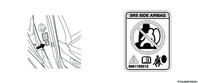
Passenger door side
4. General circuit diagram
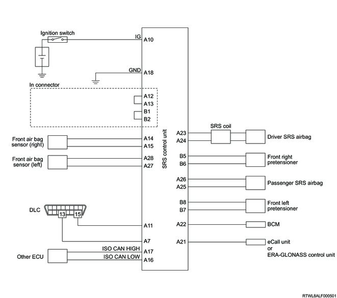
1. SRS control unit schematic circuit diagram (Except models with side airbags and curtain airbags)
2. SRS control unit outline view and connector pin layout (Except models with side airbags and curtain airbags)
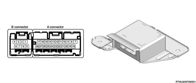
| PIN No. |
Pin function |
| 1 |
- |
| 2 |
- |
| 3 |
- |
| 4 |
- |
| 5 |
- |
| 6 |
- |
| 7 |
Diagnostic request signal input |
| 8 |
- |
| 9 |
- |
| 10 |
Ignition voltage input |
| 11 |
Batch deployment processing terminal (ACL) |
| 12 |
Connector mating check terminal |
| 13 |
Connector mating check terminal |
| 14 |
Front airbag sensor right (+) input |
| 15 |
Front airbag sensor right (-) input |
| 16 |
ISO CAN (Low) |
| 17 |
ISO CAN (High) |
| 18 |
Ground |
| 19 |
- |
| 20 |
- |
| 21 |
Deployment output to eCall unit/FRA-GLONASS control unit |
| 22 |
Deployment output to BCM |
| 23 |
Driver airbag deployment current output (High) |
| 24 |
Driver airbag deployment current output (Low) |
| 25 |
Passenger airbag deployment current output (Low) |
| 26 |
Passenger airbag deployment current output (High) |
| 27 |
Front airbag sensor left (-) input |
| 28 |
Front airbag sensor left (+) input |
| PIN No. |
Pin function |
| 1 |
Connector mating check terminal |
| 2 |
Connector mating check terminal |
| 3 |
- |
| 4 |
- |
| 5 |
Front right side pretensioner ignition current output (High) |
| 6 |
Front right side pretensioner ignition current output (Low) |
| 7 |
Front left side pretensioner ignition current output (Low) |
| 8 |
Front left side pretensioner ignition current output (High) |
3. SRS control unit schematic circuit diagram (Models with side airbags and curtain airbags)
Models without far side airbags and knee airbags
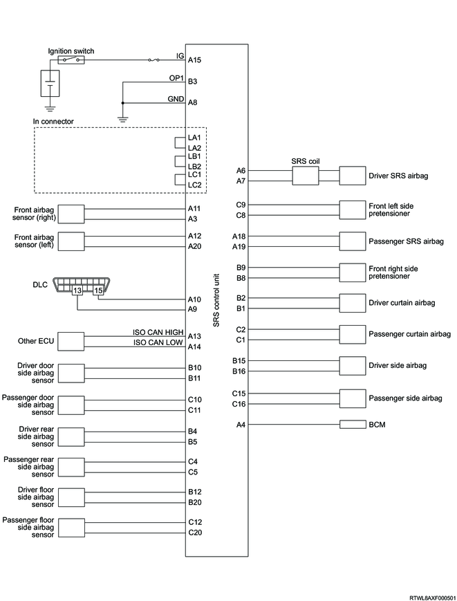
Models with far side airbags/knee airbags

4. SRS control unit outline view and connector pin layout (Models with side airbags and curtain airbags)
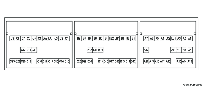
| PIN No. |
Pin function |
| 1 |
Squib incorrect assembly identification terminal (*1) |
| 2 |
Squib incorrect assembly identification terminal (*1) |
| 3 |
Front airbag sensor Right (-) input |
| 4 |
Deployment output to BCM |
| 5 |
- |
| 6 |
Driver airbag deployment current output (High) |
| 7 |
Driver airbag deployment current output (Low) |
| 8 |
Ground |
| 9 |
Diagnostic request signal input |
| 10 |
Batch deployment processing terminal (ACL) |
| 11 |
Front airbag sensor Right (+) input |
| 12 |
Front airbag sensor Left (+) input |
| 13 |
ISO CAN (High) |
| 14 |
ISO CAN (Low) |
| 15 |
Ignition voltage input |
| 16 |
Squib incorrect assembly identification terminal (*2) |
| Driver knee airbag deployment current output (High) |
|
| 17 |
Squib incorrect assembly identification terminal (*2) |
| Driver knee airbag deployment current output (Low) |
|
| 18 |
Passenger airbag deployment current output (High) |
| 19 |
Passenger airbag deployment current output (Low) |
| 20 |
Front airbag sensor Left (-) input |
| 21 |
Connector mating check terminal |
| 22 |
Connector mating check terminal |
| *1: Models without knee airbags *2: Models without far side airbags |
|
| PIN No. |
Pin function |
| 1 |
Driver curtain airbag deployment current output (Low) |
| 2 |
Driver curtain airbag deployment current output (High) |
| 3 |
Vehicle model identification terminal (*5) |
| 4 |
Driver rear side airbag sensor (+) input |
| 5 |
Driver rear side airbag sensor (-) input |
| 6 |
Squib incorrect assembly identification terminal (*3) |
| Rear right side pretensioner ignition current output (High) |
|
| 7 |
Squib incorrect assembly identification terminal (*3) |
| Rear right side pretensioner ignition current output (Low) |
|
| 8 |
Front right side pretensioner ignition current output (Low) |
| 9 |
Front right side pretensioner ignition current output (High) |
| 10 |
Driver door side airbag sensor (+) input |
| 11 |
Driver door side airbag sensor (-) input |
| 12 |
Driver floor side airbag sensor (+) input |
| 13 |
Squib incorrect assembly identification terminal (*4) |
| Far side airbag deployment current output (Low) |
|
| 14 |
Squib incorrect assembly identification terminal (*4) |
| Far side airbag deployment current output (High) |
|
| 15 |
Driver side airbag deployment current output (High) |
| 16 |
Driver side airbag deployment current output (Low) |
| 17 |
Passenger side SRS airbag cut off switch (-) input |
| 18 |
Passenger side SRS airbag cut off switch (+) input |
| 19 |
- |
| 20 |
Driver floor side airbag sensor (-) input |
| 21 |
- |
| 22 |
- |
| 23 |
Connector mating check terminal |
| 24 |
Connector mating check terminal |
| *3: Extend cab models *4: Models without far side airbags and with knee airbags *5: Models without passenger side SRS airbag cut off switches |
|
| PIN No. |
Pin function |
| 1 |
Passenger curtain airbag deployment current output (Low) |
| 2 |
Passenger curtain airbag deployment current output (High) |
| 3 |
- |
| 4 |
Passenger rear side airbag sensor (+) input |
| 5 |
Passenger rear side airbag sensor (-) input |
| 6 |
Rear left side pretensioner ignition current output (High) |
| 7 |
Rear left side pretensioner ignition current output (Low) |
| 8 |
Front left side pretensioner ignition current output (Low) |
| 9 |
Front left side pretensioner ignition current output (High) |
| 10 |
Passenger door side airbag sensor (+) input |
| 11 |
Passenger door side airbag sensor (-) input |
| 12 |
Passenger floor side airbag sensor (+) input |
| 13 |
- |
| 14 |
- |
| 15 |
Passenger side airbag deployment current output (High) |
| 16 |
Passenger side airbag deployment current output (Low) |
| 17 |
Passenger side SRS airbag ON indicator light |
| 18 |
Passenger side SRS airbag OFF indicator light |
| 19 |
Deployment output to ERA-GLONASS control unit |
| 20 |
Passenger floor side airbag sensor (-) input |
| 21 |
- |
| 22 |
- |
| 23 |
Connector mating check terminal |
| 24 |
Connector mating check terminal |