1. Component views
Brake disc No. 1, No. 2
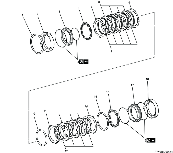
Part name
- Snap ring
- Brake cylinder No.2
- O-ring
- Brake piston No. 2
- Brake piston return spring sub-assembly No. 2
- Brake flange No. 2
- Brake disc No. 2
- Brake plate No. 2
- Brake flange No. 2
- Snap ring
- Brake flange No. 1
- Brake disc No. 1
- Brake plate No. 1
- Snap ring
- Brake piston return spring sub-assembly No. 1
- O-ring
- Brake piston No. 1
- Brake cylinder No. 1
2. Brake piston No.1 disassembly
1) While holding brake piston No. 1 by hand, apply compressed air into the oil passage of brake cylinder No. 1 as shown in the figure and remove brake piston No. 1.
Caution
- Be careful not to damage brake piston No. 1.
300 kPa { 3 kgf/cm2 / 44 psi } Compressed air

2) Remove the 2 O-rings from the brake piston No.1.
