1. Lifting instruction
Lifting instructions
If it is necessary to use lifting equipment other than an ordinary jack, confirm the identified lift points while referring to the illustration.
A vehicle should only be lifted using the lifting points illustrated in the diagram to prevent damage.
Caution
- Failure to observe the acceptable lift points may cause unsatisfactory vehicle performance or durability failure, resulting in loss of control of the vehicle.
- Do not get under the vehicle while the vehicle is only supported with a jack.
When getting under the vehicle, support the vehicle using a rigid rack.
To prevent damage (To prevent corrosion due to coating damage)
- The supporting surface is flat: Place wood pieces or rubber blocks between the floor jack and the frame, or between the rigid rack and the frame.
- The supporting surface is not flat: Place a piece of cloth on the contact surface of the floor jack or rigid rack.
Garage jack and rigid rack lifting points and supportable locations
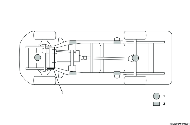
Legend
- Garage jack lifting point
- Rigid rack lifting point
- Lifting inhibition area
Front side lifting point for garage jack
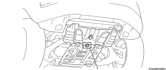
Legend
- Lifting point
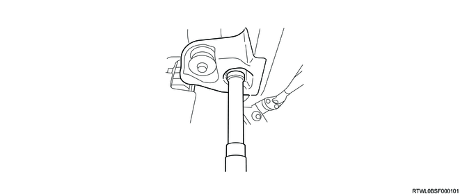
Front side lifting points of the vehicle tool kit (2WD High-Ride and 4WD models)
Front side lifting points of the vehicle tool kit (Except 2WD High-Ride and 4WD models)
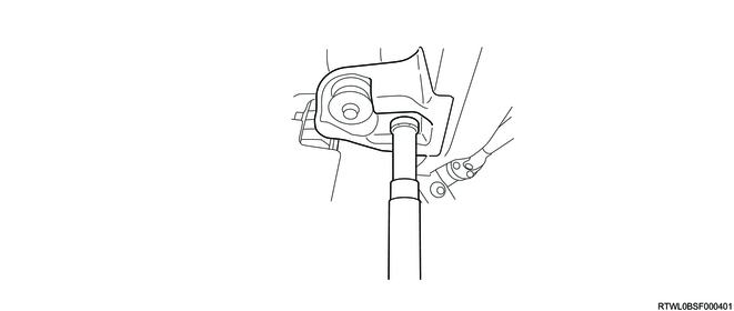
Apply the jack head to the flat part of the bracket on the frame side.
Caution
- Do not lift or apply load to the engine oil pan.
Rear side lifting points of the vehicle tool kit
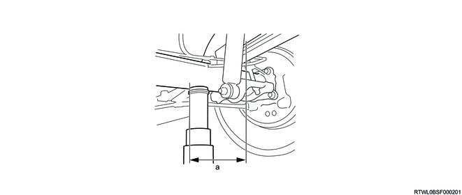
Dimensions
a: less than 90 mm { less than 3.5 in }
Set the jack at a point within 90 mm (3.5 in) from the leaf spring under the axle tube.
Align the recess on the jack head to the curved surface of the axle tube center.