1. Function, structure, operation of heating, ventilation air conditioning
1. Manual A/C
The control lever enables the cable to select the air outlet of the heater evaporator unit, adjust the temperature, and switch between inside and outside air for the blower. The fan control controls the outlet air volume in 4 levels via the blower resistor.
Control lever (Models with coolers)
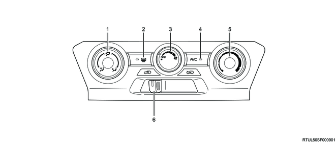
Legend
- Outlet selector dial
- Rear window defogger switch (if equipped)
- Fan speed control dial
- A/C switch
- Temperature control dial
- Air selector lever
Control lever (Models with heaters and manual A/C)
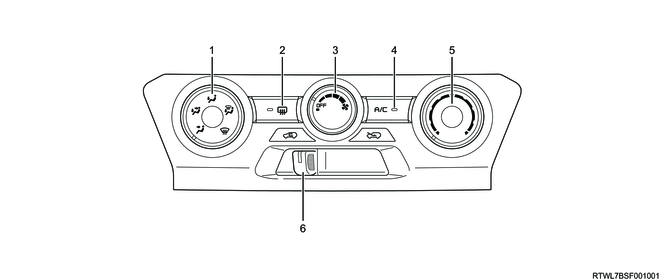
Legend
- Outlet selector dial
- Rear window defogger switch (if equipped)
- Fan speed control dial
- A/C switch
- Temperature control dial
- Air selector lever
1) Rear window defogger switch
This switch is used for defogging or defrosting the rear windows.
2) Fan speed control dial
This switch is used to control the blower motor rotation via the blower resistor, thereby controlling the air amount sent through the air outlet to the 4 levels.
3) Temperature control dial
Cooling intensity adjustment from MAX COLD to MIN COLD is available by adjusting the temperature of the air blown from the air outlet with this dial.
4) Air selector lever
By sliding this lever to the left or right, either FRESH or RECIRC can be selected.
When the air source lever is set to FRESH, outside air is continually drawn into the system.
The blower fan has a function to maintain proper ventilation by intake of the outside air into the vehicle cabin.
When the air source lever is set to RECIRC, inside air is recirculated without taking in outside air.
5) Outlet selector dial
The desired air outlet can be selected with this dial.
The air outlet to send air is selected by adjusting the position of the rotary type mode door located inside the heater evaporator unit.
This mode door adjusts the opening range of each outlet of the heater evaporator unit and blocks the opening sections, enabling selection of 3 blowing patterns.
2. Blower unit
Outside air intake (FRESH)
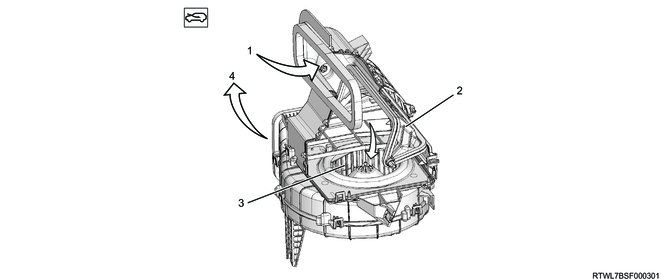
Legend
- Outside air
- Intake door
- Blower fan
- To heater evaporator unit
Inside air intake (RECIRC)
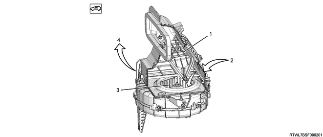
Legend
- Intake door
- Inside air
- Blower fan
- To heater evaporator unit
3. Air outlet
Type 1
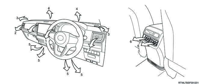
Legend
- Front center outlet
- Front side outlet
- Door windows outlet
- Windshield outlet
- Foot outlet
- Second seat outlet
1) Outlet selector switch (Type 1)
FACE
At this position, the air is supplied into the vehicle cabin through ventilation ducts 1, 2, and 6.
BI-LEVEL
At this position, the air is divided into two groups in the heater evaporator unit, and supplied into the vehicle cabin through ventilation ducts 1, 2, and 6, and foot duct 5.
FOOT
At this position, a large portion of the air is supplied to the feet through foot duct 5, and a small amount of air is supplied into the vehicle cabin through ventilation duct 2.
DEF/FOOT
At this position, air is divided into three groups in the heater evaporator unit, a large portion of air is supplied through defroster nozzles 3 and 4 and foot duct 5, and a small amount of air is supplied into the vehicle cabin through ventilation duct 2.
DEFROST
At this position, a large portion of the air is supplied to the front window through defroster nozzle 4, and a small amount of air is supplied into the vehicle cabin and to the side window through defroster nozzles 2 and 3.
Type 2
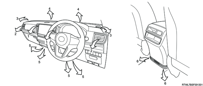
Legend
- Front center outlet
- Front side outlet
- Door windows outlet
- Windshield outlet
- Foot outlet
- Second seat outlet
2) Outlet selector switch (Type 2)
FACE
At this position, the air is supplied into the vehicle cabin through ventilation ducts 1 and 2.
BI-LEVEL
At this position, the air is divided into two groups in the heater evaporator unit, and supplied into the vehicle cabin through ventilation ducts 1, 2, and 6, and foot duct 5.
FOOT
At this position, a large portion of the air is supplied to the feet through foot ducts 5 and 6, and a small amount of air is supplied into the vehicle cabin through ventilation duct 2.
DEF/FOOT
At this position, air is divided into three groups in the heater evaporator unit, a large portion of air is supplied through defroster nozzles 3 and 4 and foot ducts 5 and 6, and a small amount of air is supplied into the vehicle cabin through ventilation duct 2.
DEFROST
At this position, a large portion of the air is supplied to the front window through defroster nozzle 4, and a small amount of air is supplied into the vehicle cabin and to the side window through defroster nozzles 2 and 3.
4. Mode door operation diagram
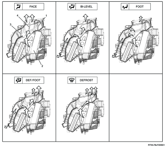
Legend
- Mode door (For DEF)
- Evaporator core
- Mode door (For FOOT)
- Mode door (For FACE)
5. Mode door structural diagram

Legend
- Mode door (For DEF)
- Evaporator core
- Mode door (For FOOT)
- Mode door (For FACE)
When set to MAX COLD (FACE mode)
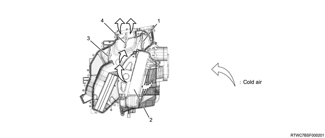
Legend
- Mode door (For DEF)
- Evaporator core
- Mode door (For FOOT)
- Mode door (For FACE)
6. A/C cycle
The A/C cycle goes through the following 4 stages, with the refrigerant changes from a liquid to a gas and back again throughout the cycle.
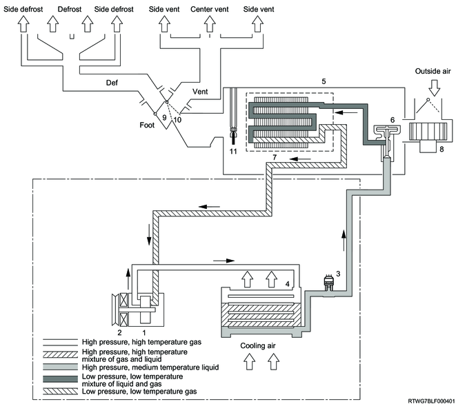
Legend
- Compressor
- Magnetic clutch
- Pressure switch
- Condenser (Integrated with receiver dryer)
- Evaporator
- Expansion valve
- Evaporator core
- Blower motor
- Mode control door (DEF/FOOT)
- Mode control door (For VENT)
- Electronic thermostat
1) Evaporation
The refrigerant changes from a liquid to a gas state inside the evaporator.
The mist form refrigerant then evaporates immediately after entering the evaporator. When the refrigerant evaporates, it steals heat from the air around the evaporator core cooling fin.
The air from which heat has been drawn cools down and is blown by the blower fan into the vehicle, lowering the temperature inside the vehicle cabin. The refrigerant liquid sent from the expansion valve and the evaporated refrigerant gas temporarily coexist in the evaporator, before the refrigerant changes its state from a liquid to a gas. During this state change from a liquid to a gas, the pressure inside the evaporator is kept low for the refrigerant to evaporate at lower temperatures. In order for this, the refrigerant gas is sucked into the compressor and then discharged from the evaporator.
2) Compression
The refrigerant is compressed by the compressor until it easily liquefies at room temperature.
Vaporized refrigerant in the evaporator is then sucked into the compressor. This function keeps the refrigerant in the evaporator at a low pressure and ensures that the liquid refrigerant will evaporate even at low temperatures close to 0°C {32°F}. The refrigerant that is sucked into the compressor is compressed inside the cylinder to raise its pressure so that it is easily liquefied by the outside air at room temperature.
3) Condensation
The refrigerant in the condenser is cooled by the outside air and changes from a gas to a liquid.
High temperature, high pressure gas from the compressor is liquefied by being cooled by the condenser and outside air, and is stored in the receiver dryer.
The heat that is dissipated by the high temperature and high pressure refrigerant from the compressor to the outside air is known as condensing heat. This heat quantity is the sum of the heat taken by the refrigerant from inside the vehicle cabin via the evaporator and the work performed during compression.
4) Expansion
The expansion valve lowers pressure to allow for the easy evaporation of refrigerant liquid.
The process where the pressure is lowered before the liquefied refrigerant is sent to the evaporator to ease evaporation is known as expansion. The expansion valve also controls the flow amount of the refrigerant liquid while lowering its pressure. In other words, the amount of refrigerant liquid to be evaporated inside the evaporator is determined by the amount of heat taken in at the specified evaporating temperature. Because of this, it is important to control the amount of refrigerant so that it is not less or more than the necessary amount.
7. A/C system functions
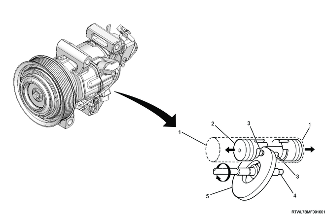
1) A/C compressor
The compressor compresses the low pressure and low temperature refrigerant vapor from the evaporator into a high pressure and high temperature refrigerant vapor, and sends it to the condenser to ease dissipation of heat to the outside air.
4JJ3 (Auto A/C, except M/T models (Euro 5 or above))
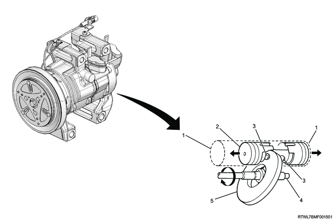
Legend
- Cylinder
- Piston
- Ball
- Shaft
- Swashplate
4JJ3 (Auto A/C, M/T models (Euro 5 or above))
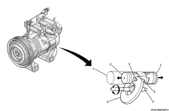
Legend
- Cylinder
- Piston
- Ball
- Shaft
- Swashplate
4JJ3 (Manual A/C, except M/T models (Euro 5 or above))
Legend
- A/C compressor
4JJ3 (Manual A/C, M/T models (Euro 5 or above))
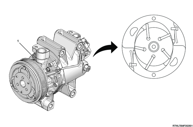
Legend
- A/C compressor
RZ4E (Auto A/C)
Legend
- Cylinder
- Piston
- Ball
- Shaft
- Swashplate
RZ4E (Manual A/C)
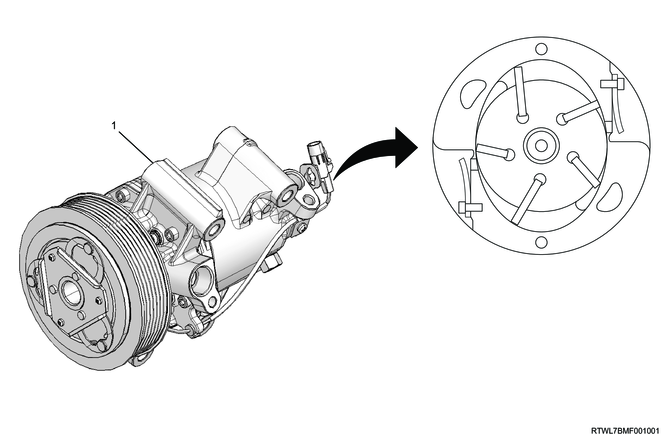
Legend
- A/C compressor
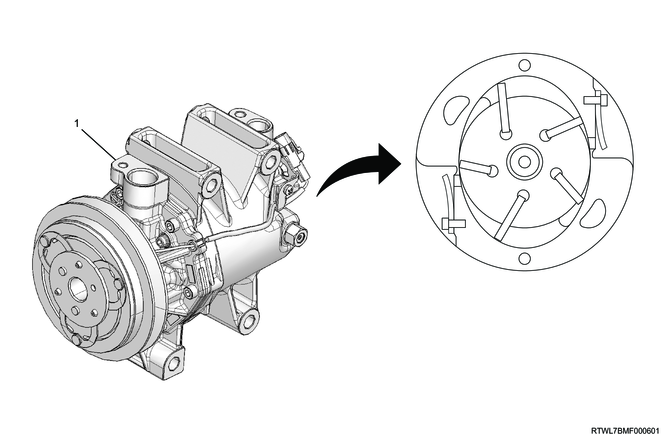
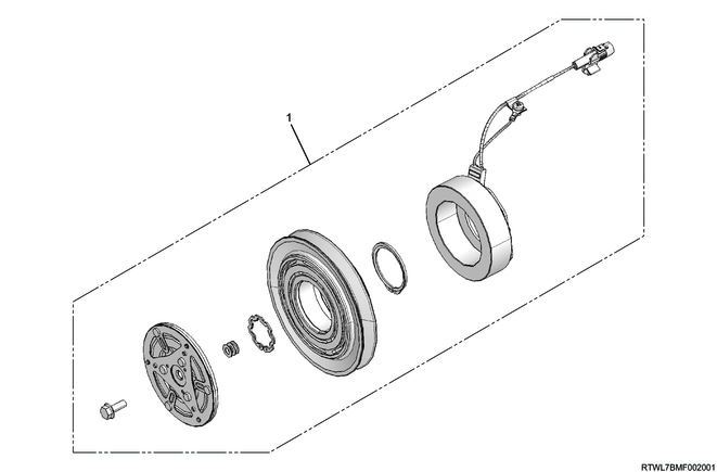
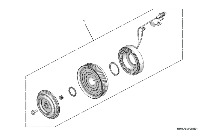
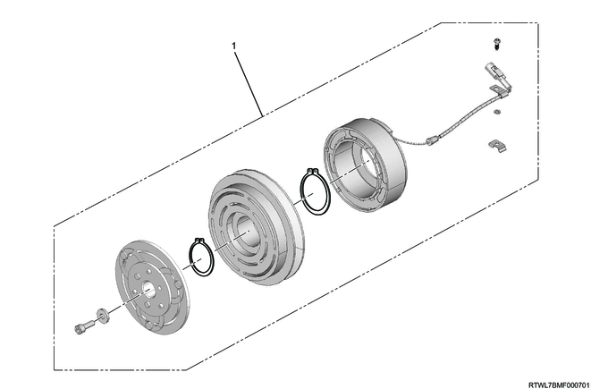
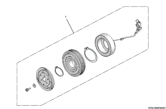
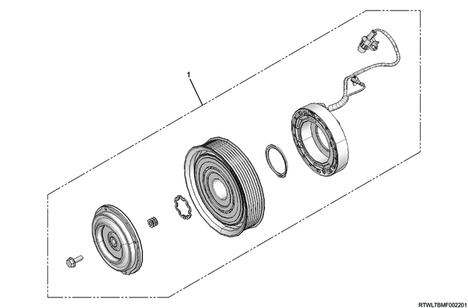
2) Magnetic clutch
The compressor is driven by the drive belt from the engine crank pulley. It is, however, not desirable for the compressor to be driven every time the engine is started because it imposes a significant load on the engine. Therefore, the magnetic clutch transmits the power from the engine when the A/C is ON to activate the compressor. It cuts the power to the compressor from the engine when the A/C is turned OFF.
4JJ3 (Auto A/C, except M/T models (Euro 5 or above))
Legend
- Magnetic clutch
4JJ3 (Auto A/C, M/T models (Euro 5 or above))
Legend
- Magnetic clutch
4JJ3 (Manual A/C, except M/T models (Euro 5 or above))
Legend
- Magnetic clutch
4JJ3 (Manual A/C, except M/T models (Euro 5 or above))
Legend
- Magnetic clutch
RZ4E (Auto A/C)
Legend
- Magnetic clutch
RZ4E (Manual A/C)

Legend
- Magnetic clutch
3) Condenser
The condenser forces the high temperature and high pressure refrigerant gas sent from the compressor to be cooled down and liquefied by the outside air. If the condenser is clogged or the air flow into the condenser cooling fin is blocked, the cooling capacity of the condenser will be insufficient causing the pressure of the refrigerant cycle to raise and the load on the engine to increase. When the operation of the condenser is normal, the refrigerant discharge line of the condenser is usually cooler than the intake line.
The electric fan is also mounted to boost the cooling effect.

Legend
- Condenser (Integrated with receiver dryer)
4) Receiver dryer
The amount of refrigerant circulating varies with the conditions of the A/C cycle. To operate smoothly in accordance with changes in the amount circulating, the necessary amount of refrigerant for the A/C cycle is stored.
Bubbles of the refrigerant gas are mixed in with the liquefied refrigerant from the condenser. If refrigerant containing gas bubbles is sent to the expansion valve, the cooling capacity may deteriorate significantly. So it separates the liquid from the gas bubbles and sends only the liquid to the expansion valve.
Any dust and water mixed into the circulating refrigerant are removed using the filter and the dryer inside the receiver dryer.
Clogging in the receiver dryer may cause the A/C's performance to deteriorate. When clogging occurs at the inlet of the receiver dryer, the refrigerant pressure rises, while the pressure lowers when clogging occurs at the outlet. In both cases, cooling can hardly take place. If the pipe at the outlet of the receiver dryer is unusually cold, it indicates that clogging has occurred.
5) Pressure switch
The pressure switch is installed to the high pressure pipe. It monitors unusually high refrigerant pressure on the high pressure switch side. It monitors refrigerant leaks on the low pressure switch side to prevent the compressor from seizing. The magnetic clutch is turned ON or OFF at each set pressure.
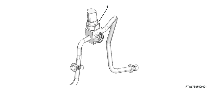
Legend
- Pressure switch
| Control |
Refrigerant pressure |
Magnetic clutch |
| Low pressure side switch |
176 to 216 kPa { 1.8 to 2.2 kgf/cm2 / 26 to 31 psi } |
OFF |
| 195 to 255 kPa { 2.0 to 2.6 kgf/cm2 / 28 to 37 psi } |
ON |
|
| High pressure side switch |
2,840 to 3,040 kPa { 29.0 to 31.0 kgf/cm2 / 412 to 441 psi } |
OFF |
| 2,050 to 2,650 kPa { 20.9 to 27.0 kgf/cm2 / 297 to 384 psi } |
ON |
6) Evaporator
The evaporator changes the low pressured, low temperature liquid refrigerant in mist form supplied from the expansion valve into a gas via heat exchange with the air that is supplied from the blower motor. Vaporization heat that is generated when the liquid refrigerant evaporates into vapor cools down the evaporator and the evaporator core fin, which in turn cools down the air sent from the blower motor. Moisture in the air is cooled and forms water droplets, and the vehicle is dehumidified by removing these droplets from the vehicle.
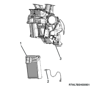
7) Expansion valve
The expansion valve is a uniform external pressure type valve and is mounted to the inlet of the evaporator core.
The high pressure liquid refrigerant sent from the receiver dryer undergoes a squeezing action when it passes through the expansion valve, which changes it into a low pressure liquid refrigerant in mist form before it is sent to the evaporator core.
This expansion valve is comprised of a thermosensor, diaphragm, ball valve, spring adjustment screw, etc. The thermosensor is in contact with the evaporator outlet pipe, and controls the refrigerant flow amount by converting the temperature variation into pressure to operate the diaphragm.
The expansion valve also adjusts the refrigerant flow amount as it ensures efficient utilization of each device of the A/C cycle. Therefore, expansion valve malfunctions will cause both the outlet pressure and inlet pressure values to drop, resulting in insufficient evaporator cooling performance.
Legend
- Evaporator core
- Expansion valve
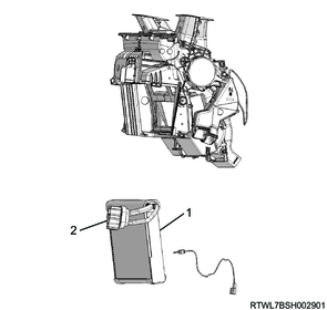
8) Evaporator temperature sensor
The evaporator temperature sensor is mounted to the outlet of the evaporator core, and detects the temperature of the air that passes through the evaporator core.
The OFF value is 2.7°C {36.9°F} and the ON value is 5.0°C {41.0°F}.
Legend
- Evaporator core
- Evaporator temperature sensor
- Heater evaporator unit
9) Refrigerant piping
Conditions similar to the following will occur if the refrigerant piping is clogged.
Low pressure hose
When clogging occurs in the low pressure hose, the compressor inlet and outlet pressures drop, and cooling capacity is lost.
High pressure hose
When clogging occurs in the high pressure hose, leakage from the discharge line usually occurs.
High pressure pipe
When clogging occurs in the high pressure pipe, the pressures at both of the outlet and inlet sides drop, resulting in insufficient cooling.
Also, the high-pressure flexible hose is a low leakage-type hose that has a layer of nylon at their innermost portions.
This design allows for quick joint attachment in order to prevent refrigerant from leaking into the atmosphere when connecting service tools.
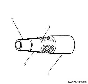
Legend
- Polyester
- Outside surface rubber layer
- Inside surface rubber layer
- Nylon layer
Manual A/C
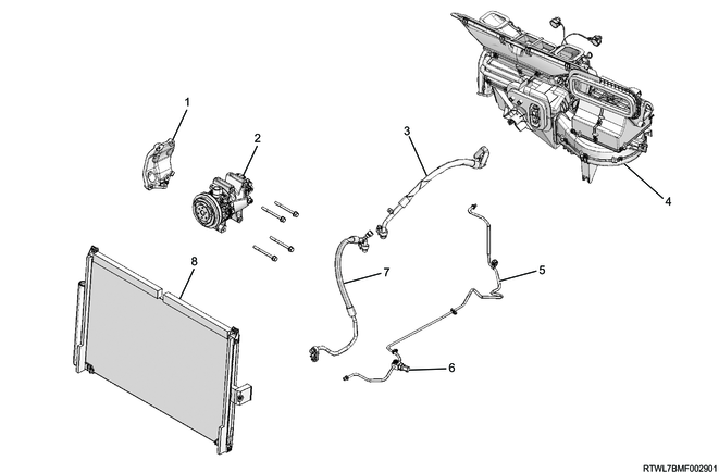
Legend
- A/C compressor bracket
- A/C compressor
- A/C hose
- Evaporator unit
- A/C pipe
- Pressure switch
- A/C hose
- Condenser (Integrated with receiver dryer)