1. Emergency call system overview
The Emergency Call System (eCall System) is a system that makes an emergency call using the Global Navigation Satellite System (GNSS). The eCall System is activated when the airbag is deployed or when the SOS button is pressed. When the eCall System is activated, an emergency call is made to the emergency call center, and at the same time, the vehicle location, vehicle identification number, etc., are sent. After that, a voice call is started with the operator of the emergency call center, and if there is no response from the occupant, the operator immediately dispatches an emergency service for rescue.
Note
- Do not press the SOS button except in an emergency. If the SOS button is accidentally pressed, tell the operator about the situation by a voice call.
- If the emergency call system does not operate normally, request for a rescue using a public telephone, etc., around the vehicle.
Diagram of input/output

2. Emergency call system
1. System activation
When the ignition switch is turned ON, the indicator light illuminates in red for 3 to 4 seconds, illuminates in green for approximately 4 seconds, and then turns OFF. If there is a malfunction in the system, the indicator light remains illuminating in red.
Legend
- SOS button
- Indicator light
2. System operation
The emergency call system is activated when the airbag is deployed or when the SOS button is pressed for 1 second or more. When the emergency call system is activated, the audio is automatically muted so that the voice call between the operator of the emergency call center and the occupant is not interrupted.
Note
- When connected to the operator of the emergency call center, the voice call cannot be canceled from the vehicle.
Emergency call system operation diagram
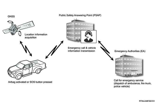
1) Emergency call
It is sent to the emergency call center when the airbag is deployed or the SOS button is pressed.
2) Identification of location
Vehicle information such as the occurrence location, vehicle traveling direction, vehicle model, and number of occupants is sent to the emergency call center.
3) Information acquisition
A voice call between the emergency call center operator and the occupant starts. If there is no response from the occupant, the operator immediately dispatches an emergency service for rescue.
3. Indicator light/alarm
Depending on the operating state of the emergency call system, the illumination/flashing state and lighting color of the indicator light are different. An alarm also sounds depending on the situation.
| Condition |
Color (Red/Green) |
Illuminated or flashing |
Alarm sound |
| During initial diagnosis (Ignition switch is turned ON) |
Red (3 to 4 seconds) Green (approx. 4 seconds) |
Illuminated |
- |
| During emergency call |
Green |
Flashing |
- |
| When voice call starts |
Green |
Illuminated |
One continuous beep |
| During voice call |
Green |
Illuminated |
- |
| Emergency call connection failure |
Red |
Flashing |
A series of short beep with pauses |
| When the battery built into eCall unit needs to be replaced |
Red |
Illuminated |
A series of long beeps |
| When the contract of the SIM built into eCall unit will expire in less than 6 months. |
Red |
Illuminated |
A series of long beeps |
| When system malfunctions |
Red |
Illuminated |
A series of long beeps |
3. Emergency call system components
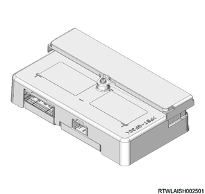
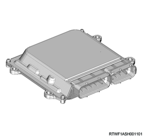
1. eCall unit
The eCall unit is installed in the center of the instrument panel. The eCall unit activates the emergency call system when the airbag is deployed or when the SOS button is pressed. When the system is activated, the battery built into the eCall unit is used. In addition, the eCall unit has a self-diagnosis function. If a malfunction occurs in the system, the indicator light (red) is illuminated and an alarm sounds from the speaker.
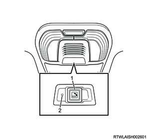
2. SOS button / Indicator light
The SOS button is integrated with the indicator light and is installed to the overhead console. The emergency call system is activated automatically only when the airbag is deployed. In an emergency such as a traffic accident and sudden illness, the emergency call system can be activated manually by pressing the SOS button for 1 second or more.
The indicator light flashes in green during an emergency call and illuminates in green during a voice call. Also, if the battery built into the eCall unit needs to be replaced or if there is a malfunction in the system, the indicator light remains illuminating in red.
Legend
- SOS button
- Indicator light
Note
- The SOS button itself illuminates when the light control switch is in the taillight position, AUTO position (night-time only) or headlight position.
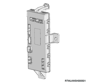
3. Antenna
The GNSS antenna and TEL antenna are integrated into an antenna, and the antenna is installed in the center of the instrument panel. The GNSS antenna receives GNSS signals, and the TEL antenna transmits emergency calls to the emergency call center when the emergency call system is activated.

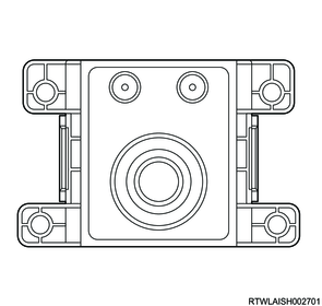
4. Speaker microphone
The microphone and speaker are integrated into the speaker microphone, which is installed in the overhead console. When the emergency call system is activated, a voice call can be made between the emergency call center operator and the occupant via the speaker microphone. If there is no response from the occupant, the operator immediately dispatches an emergency service for rescue. Also, if there is a malfunction in the system, an alarm sounds from the speaker.
Note
- The volume of the microphone and speaker cannot be adjusted.
5. ECM
The ECM sends vehicle speed signals to the eCall unit via the CAN communication circuit.
6. SRS control unit
The SRS control unit sends deployment signals to the eCall unit via the deployment signal circuit. The deployment signals are sent from the SRS control unit to the eCall unit via CAN communication as well.

7. BCM
The BCM sends the hazard warning flasher switch and turn signal switch signals to the eCall unit via the CAN communication circuit.
8. Instrument panel cluster
The instrument panel cluster sends seat belt switch signals to the eCall unit via the CAN communication circuit.
9. Audio
When the audio receives the mute signals from the eCall unit via the MUTE output circuit while the emergency call system is operating, the audio stops the sound output.
4. Emergency call system component views
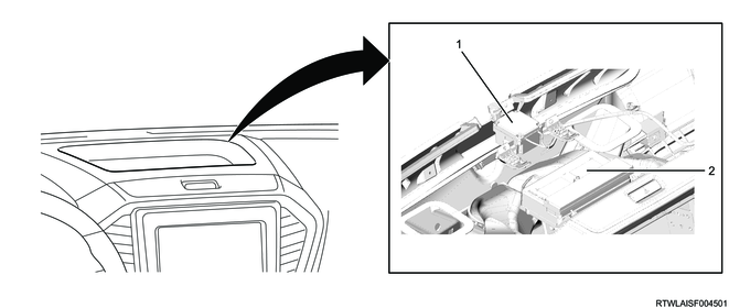
Legend
- Antenna
- eCall unit
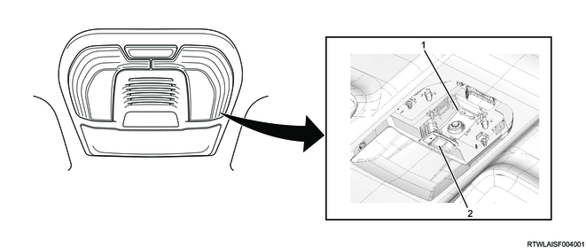
Legend
- Speaker microphone
- SOS button
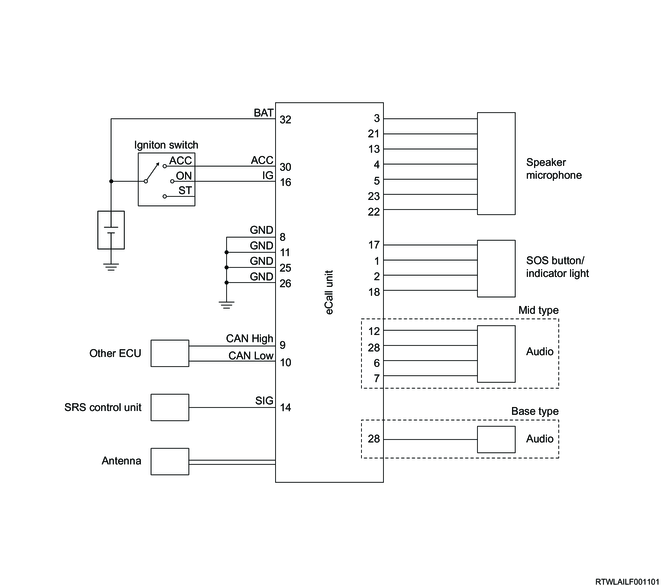
5. General circuit diagram
1. eCall unit general circuit diagram
2. eCall unit outline view and connector face
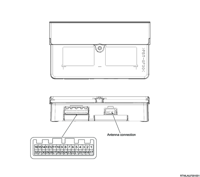
| Pin No. |
Pin function |
| 1 |
Indicator light (red) control |
| 2 |
Indicator light (green) control |
| 3 |
Speaker microphone power supply |
| 4 |
Speaker microphone input (+) |
| 5 |
Speaker microphone input (-) |
| 6 |
Speaker microphone output (+) |
| 7 |
Speaker microphone output (-) |
| 8 |
Ground |
| 9 |
CAN (High) |
| 10 |
CAN (Low) |
| 11 |
Ground |
| 12 |
UART communication |
| 13 |
UART communication |
| 14 |
Air bag active PWM signal |
| 15 |
- |
| 16 |
Ignition power supply |
| 17 |
SOS button signal |
| 18 |
SOS button / Indicator light ground |
| 19 |
- |
| 20 |
- |
| 21 |
Speaker microphone ground |
| 22 |
Speaker output (-) |
| 23 |
Speaker output (+) |
| 24 |
- |
| 25 |
Ground |
| 26 |
Ground |
| 27 |
- |
| 28 |
Mute control |
| 29 |
- |
| 30 |
Accessory power supply |
| 31 |
- |
| 32 |
Battery power supply |