1. Body control description
The central gateway control unit has the following functions.
- Signal relay function
- Network management function
- Self-diagnosis function
2. Function of body control
1. Signal relay function
1) Control information relay
The central gateway control unit receives the control information from each control unit, instrument panel cluster, etc., via the Powertrain, Chassis, Body, and Information CAN communication circuits. The central gateway control unit sends the received signals to each different CAN communication circuit.
2) Diagnostic information relay
The central gateway control unit communicates with the scan tool via the Diagnostic CAN communication circuit. Also, the units not connected to the Diagnostic CAN communication circuit communicate with the scan tool via the central gateway control unit because they cannot communicate directly with the scan tool.
2. Network management function
Even if the ignition switch is OFF, the central gateway control unit enables the signal relay function when it receives the CAN signals.
3. Self-diagnosis function
If the central gateway control unit functions do not operates normally, a DTC is set.
3. Body controls components
1. Central gateway control unit
The central gateway control unit is installed in the driver side instrument panel. 5 CAN communication circuits of Powertrain, Chassis, Body, Information, and Diagnostic are connected to the central gateway control unit. The central gateway control unit has the signal relay function and network management function to relay the control information and diagnosis information sent from each unit.
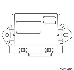
4. Body controls component views
Note
- The illustration shows an RHD model.

Legend
- Central gateway control unit
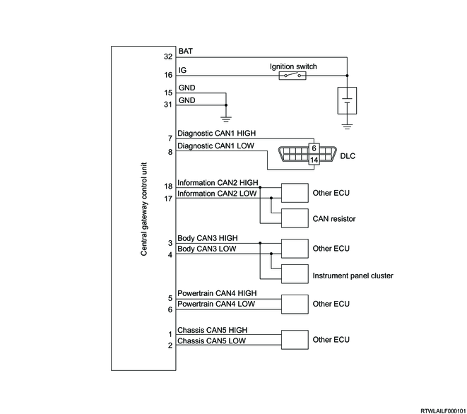
5. General circuit diagram
1. Central gateway control unit general circuit diagram
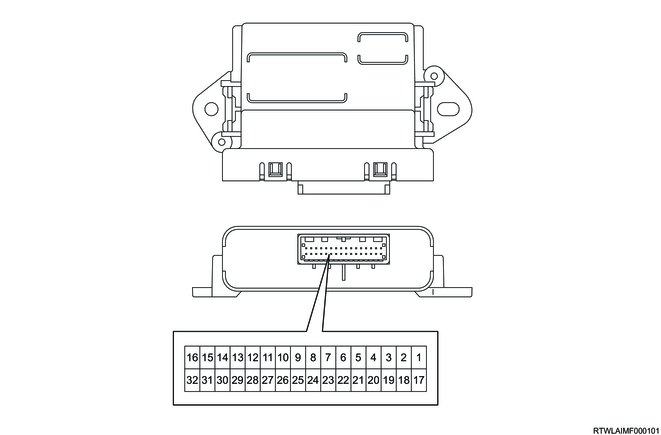
2. Central gateway control unit outline view and connector face
| Pin No. |
Pin function |
| 1 |
Chassis CAN5 (High) |
| 2 |
Chassis CAN5 (Low) |
| 3 |
Body CAN3 (High) |
| 4 |
Body CAN3 (Low) |
| 5 |
Powertrain CAN4 (High) |
| 6 |
Powertrain CAN4 (Low) |
| 7 |
Diagnostic CAN1 (High) |
| 8 |
Diagnostic CAN1 (Low) |
| 9 |
- |
| 10 |
- |
| 11 |
- |
| 12 |
- |
| 13 |
- |
| 14 |
- |
| 15 |
Ground |
| 16 |
Ignition power supply |
| 17 |
Information CAN2 (Low) |
| 18 |
Information CAN2 (High) |
| 19 |
- |
| 20 |
- |
| 21 |
- |
| 22 |
- |
| 23 |
- |
| 24 |
- |
| 25 |
- |
| 26 |
- |
| 27 |
- |
| 28 |
- |
| 29 |
- |
| 30 |
- |
| 31 |
Ground |
| 32 |
Battery power supply |