1. Wireless Access Module overview
The wireless access module is classified into 3 versions depending on the vehicle equipped system.
| Function |
Wireless Access Module |
||
| Hi-version |
Mid-version |
Lo-version |
|
| Passive entry and start system |
O |
- |
- |
| Keyless entry system |
O |
O |
- |
| Immobilizer |
O |
△ |
O |
| Tire pressure monitoring system |
O |
O |
- |
| Emergency |
O |
- |
- |
| Power mode switching |
O |
- |
- |
| Battery protection |
O |
- |
- |
| Warning |
O |
O |
O |
| Customize |
O |
- |
- |
This section describes the wireless access module of the Mid-version/Lo-version (except passive entry and start system).
Refer to Function, structure, operation of tire pressure monitoring system for the details on the tire pressure monitoring functions.
Mid-version/Lo-version
1. Mid-version
Wireless access module Mid-version equipped models can lock or unlock doors from a long distance by the keyless entry key. The Mid-version consists of the following components, and controls the keyless entry function and immobilizer function.
Mid-version system schematic
Mid-version input/output diagram
2. Lo-version
The wireless access module (Lo-version equipped models) controls only the immobilizer function.
Lo-version system schematic

Lo-version input/output diagram
2. Keyless entry function
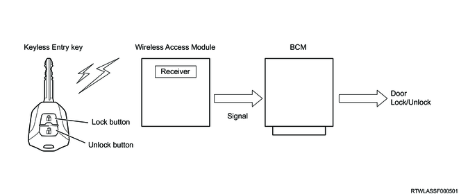
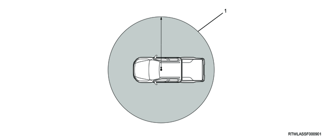
Locking/unlocking of the doors is possible using the lock button/unlock button on the keyless entry key within the range from approximately 20 m (approximately 66 ft) to maximum approximately 50 m (approximately 164 ft) from the center of the vehicle.
If the lock button or unlock button on the keyless entry key is pressed, the keyless entry key sends radio signals to the receiver in the wireless access module. When the wireless access module receives radio signals, it outputs a locking or unlocking command to the BCM. The BCM activates the door lock actuator, locking/unlocking the doors. As an operation of the answerback, the flasher control is also performed.
Schematic drawing of locking/unlocking using the keyless entry function
Range in which locking/unlocking using the keyless entry function is possible
Legend
- Operating range for locking and unlocking
The following functions will operate when the lock button on the keyless entry key is pressed.
- All the doors are locked.
- The hazard warning flasher flashes once.
The following functions will operate when the unlock button on the keyless entry key is pressed.
- All the doors are unlocked.
- The hazard warning flasher flashes twice.
Note
- If the doors are unlocked for approximately 30 seconds without opening one of the doors after unlocking the doors, door locking will be requested to the BCM.
3. Selective unlock function
1. Selective unlock function
The selective unlock function is a function that unlocks the doors in steps depending on the number of times the driver performs an unlocking operation from outside the vehicle. When the wireless access module detects the first unlocking operation, it sends the command to unlock only the driver-side door to the BCM. Furthermore, if the second unlocking operation is detected within 3 seconds after the first unlocking operation, it sends the command to unlock all the doors other than the driver-side door to the BCM.
Also, if the unlock button of the keyless entry key is pressed to perform the second unlock operation after 3 seconds or more passes from the first unlock operation, the wireless access module sends the command to unlock only the driver-side door again to the BCM.
<Activation preconditions>
- All the doors and tailgate are locked.
<Operating conditions>
- The doors are unlocked by the unlock button of the keyless entry key.
Note
- The selective unlock function is only equipped on models for South Africa.
4. Immobilizer function
The immobilizer function consists of an immobilizer coil, wireless access module, ECM, and a key with the built-in transponder chip. Together with the ECM, the wireless access module controls the engine startup. While the system is activated, the ECM controls the fuel injection system and the starter cut relay in order to prevent the engine from starting.
Immobilizer operation

When the ignition switch is turned ON, the wireless access module starts authentication of the transponder via the immobilizer coil. When the wireless access module sends a specific signal to the transponder, the transponder sends a response signal back to the wireless access module. This signal is sent via the immobilizer coil.
When the transponder authentication is complete, the wireless access module starts authentication with the ECM. The ECM sends a specific request signal to the wireless access module, and the wireless access module sends a response signal back to the ECM. This signal is sent via CAN communication.
After authentication with the ECM is complete, it is possible to start the engine.
5. Warning function
The warning is issued by the wireless access module via the MID in the instrument panel cluster under the following conditions.
| Warning and MID |
Condition |
| Check engine hood |
If door locking is attempted by keyless entry key when the engine hood is open. |
| Check system |
Any of the following is operated when an error occurs in the system related to the wireless access module (WAM). ・Door locking is attempted by pressing the keyless entry key. ・The ignition switch is turned ON. |
Note
- Check engine hood is displayed on the MID only for models with anti-theft system.
6. Wireless Access Module controls components
1. Keyless entry key
The doors can be locked or unlocked by operating the button within approximately 20 m of the vehicle. If 2 or more keyless entry keys are operated at the same time, their operation will be unstable due to radio wave interference. It is possible to register a maximum of 5 keyless entry keys. The battery life of the keyless entry key is approximately 2 years, though it varies depending on usage conditions.
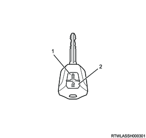
Legend
- Lock button
- Unlock button
2. Transponder key
The transponder key does not have a power supply, and has a transponder chip built into the grip section. The transponder chip is energized by electromagnetic waves emitted from the immobilizer coil that is installed to the outer circumference of the key lock cylinder. The engine can be started only with correctly programmed transponder keys. A maximum of 5 transponder keys can be registered through additional programming.
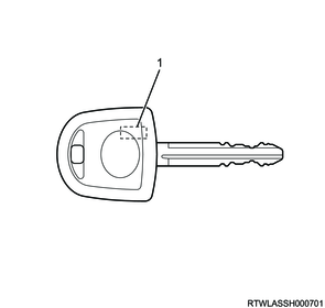
Legend
- Transponder chip
3. Immobilizer coil
The immobilizer coil is installed on the outer circumference of the key lock cylinder. When the wireless access module performs authentication with the transponder chip built into the keyless entry key or transponder key, the immobilizer coil also supplies power to the transponder chip via radio waves.
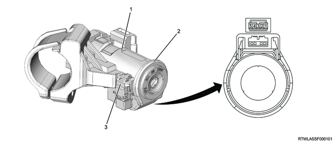
Legend
- Steering lock section
- Immobilizer coil
- Key reminder switch (Models with keyless entry system)
| PIN No. |
Pin Function |
| 1 |
Immobilizer coil (+) |
| 2 |
- |
| 3 |
- |
| 4 |
- |
| 5 |
Immobilizer coil (-) |
4. Key monitor warning light
If a malfunction occurs in the wireless access module, the key monitor warning light illuminates or blinks to inform the driver of a malfunction in the system.
7. Wireless Access Module controls component views
RHD

Legend
- Wireless access module
LHD
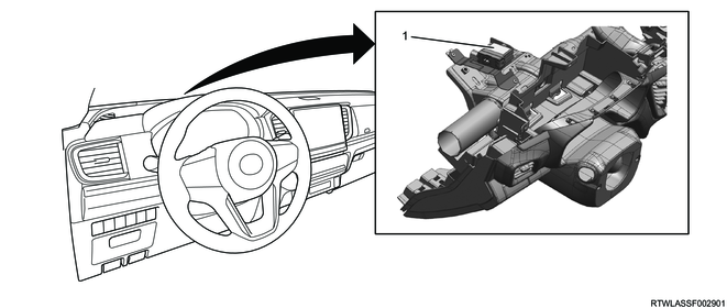
Legend
- Wireless access module
8. General circuit diagram
1. Wireless Access Module (Mid-version/Lo-version) general circuit diagram
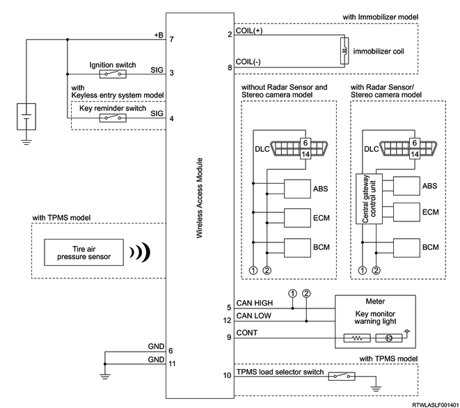
2. Wireless Access Module (Mid-version/Lo-version) outline view, connector pin layout diagram
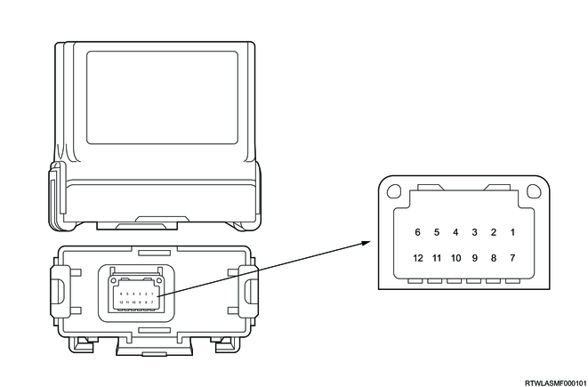
| PIN No. |
Pin Function |
| 1 |
- |
| 2 |
Immobilizer coil (+) |
| 3 |
Ignition switch signal |
| 4 |
Key reminder switch signal (Models with keyless entry system) |
| 5 |
CAN high signal |
| 6 |
Power ground |
| 7 |
Battery power supply |
| 8 |
Immobilizer coil (-) |
| 9 |
Key monitor warning light control |
| 10 |
- |
| 11 |
Signal ground |
| 12 |
CAN low signal |