1. Wireless Access Module overview
The wireless access module is classified into 3 versions depending on the vehicle equipped system.
| Function |
Wireless Access Module |
||
| Hi-version |
Mid-version |
Lo-version |
|
| Passive entry and start system |
O |
- |
- |
| Keyless entry system |
O |
O |
- |
| Immobilizer |
O |
△ |
O |
| Tire pressure monitoring system |
O |
O |
- |
| Emergency |
O |
- |
- |
| Power mode switching |
O |
- |
- |
| Battery protection |
O |
- |
- |
| Warning |
O |
O |
O |
| Customize |
O |
- |
- |
This chapter describes the wireless access module of the Hi-version (passive entry and start system).
Refer to Function, structure, operation of tire pressure monitoring system for the details on the tire pressure monitoring functions.
Hi-version
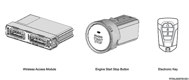
For wireless access module Hi-version equipped models, if the electronic key is carried, it is possible to lock/unlock doors and start the engine without inserting a mechanical key. The Hi-version consists of the following components and controls the passive entry and start system function, keyless entry function, and immobilizer function.
Hi-version system schematic
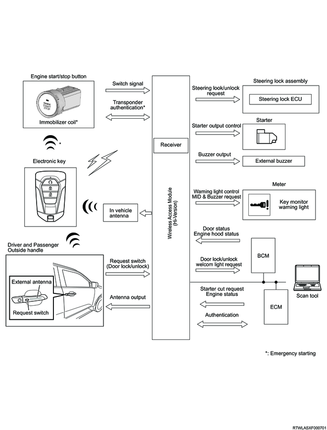
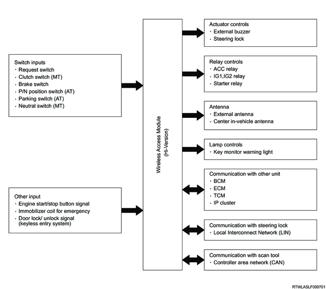
Hi-version input/output diagram
2. Passive entry and start system function
1. Passive entry and start system function
With the electronic key within 80 cm (32 in) of the outside handle, the doors will lock/unlock when the outside handle request switch is pressed. Locking and unlocking the doors using the passive entry and start system function is only possible with the power mode (ignition switch) OFF.
If the outside handle request switch is pressed, the wireless access module sends radio signals from the external antenna to the electronic key. After receiving these radio signals, the electronic key will send radio signals to the receiver in the wireless access module. When the wireless access module receives radio signals, it outputs locking or unlocking command to the BCM. The BCM forces the door lock actuator to operate, locking/unlocking the door.
Schematic drawing of locking/unlocking using the passive entry and start system function

Range in which locking/unlocking using the passive entry and start system function is possible
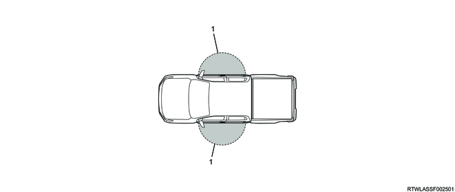
Legend
- Operating range for locking and unlocking
When the doors are locked by request switch operation, the following answerback operation is performed.
- The hazard warning flasher flashes once.
- The external buzzer sounds once.
When the doors are unlocked by request switch operation, the following answerback operation is performed.
- The hazard warning flasher flashes twice.
- The external buzzer sounds twice.
Note
- If the doors are unlocked for approximately 30 seconds without opening one of the doors after unlocking the doors, door locking will be requested to the BCM.
2. Welcome light/walk away door lock function
The wireless access module communicates with the electronic key within the range of the following detection area B via the external antenna in order to detect that the driver with the electronic key comes close to or goes away from the vehicle. The wireless access module uses this communication to control the following functions.
Range in which illuminating/locking using the welcome light/walk away door lock function is possible
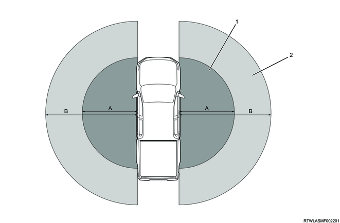
Legend
- A: Operation range of welcome light (Within 2.0 m [6 ft])
- B: Operation range of walk away door lock (3.0 m [9 ft] or more)
Note
- The operation range of the walk away door lock may reach up to 5.0 m (16 ft) depending on the communication state of the external antenna and electronic key.
1) Welcome light function
Illumination diagram of welcome light function
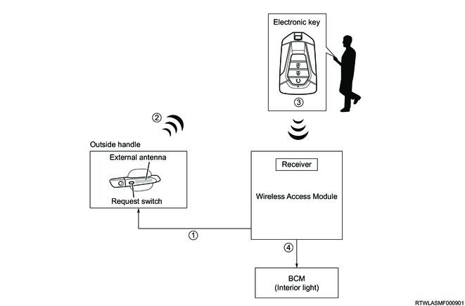
When the wireless access module detects that the driver enters the detection area with the electronic key, it commands the BCM to illuminate the dome light for 30 seconds.
Note
- The vehicle initial setting for the welcome light function is Disable. To set the welcome light function Enable, change the settings using the MID user customization function
<Operating preconditions>
- The welcome light function is Enable using the user customization function.
- The doors are locked by the keyless entry or passive entry function outside the vehicle when the power mode is OFF.
- The driver is away from detection area B within 5 minutes with the electronic key.
<Operating conditions>
- The driver enters detection area A (approximately 2.0 m [6 ft] of the vehicle) within 30 seconds after entering detection area B with the electronic key.
<Deactivation/non-operating conditions>
- 5 days (120 h) has passed after the preconditions were met.
- Before entering detection area A, the doors is unlocked using the keyless entry function or the remote engine start function is activated.
- The doors are unlocked by the emergency key without the emergency key.
- The driver does not walk away from detection area B (maximum of 5.0 m [16 ft] from the vehicle) for 5 minutes or more with the electronic key.
Note
- If any one of the electronic keys is in the vehicle, the welcome light does not function even if the door is locked with a keyless entry function from outside the vehicle.
2) Walk away door lock function
Locking diagram of walk away door lock function
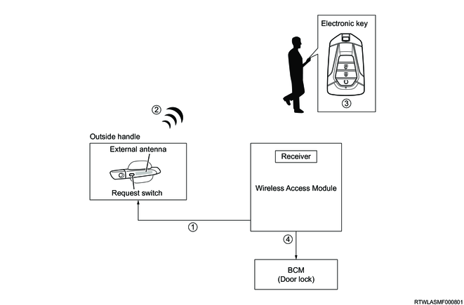
When the wireless access module detects that the driver closes the door with the electronic key from outside the vehicle but moves away from the detection area without locking, it outputs an alarm by the external buzzer and a locking command to the BCM. The BCM locks the doors through operation of the door lock actuator.
Note
- Enable/Disable of the walk away door lock can be changed using the MID user customization function. (The default setting is Enable.)
- Enable/Disable of the walk away door lock chime can be switched using the MID user customization function. (The default setting is Disable.)
<Operating preconditions>
- The walk away door lock function is Enable using the instrument panel cluster customization function.
- The electronic key is not inside the vehicle with the engine stopped.
- The vehicle can be locked with the doors closed.
<Operating conditions>
- The driver is away from detection area B with the electronic key.
<Stop conditions>
- The driver does not walk away from detection area B (maximum of 5.0 m [16 ft] from the vehicle) for 30 seconds with the electronic key.
- Open the door.
- Lock with the keyless entry or passive entry function from outside the vehicle.
<Walk away door lock warning>
If the function does not operate properly, the wireless access module sounds the external buzzer 10 times.
- The electronic key does not exist in detection area B when the preconditions are checked.
- The electronic key is thrown into the vehicle from the window after the operational preconditions are met.
- The driver does not walk away from detection area B (maximum of 5.0 m [16 ft] from the vehicle) for 30 seconds with the electronic key.
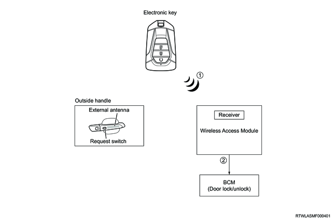
3. Keyless entry function
Locking or unlocking of the doors is possible using the lock button or unlock button on the electronic key within the range from approximately 20 m (approximately 66 ft) to maximum approximately 50 m (approximately 164 ft) from the center of the vehicle.
If the lock button or unlock button on the electronic key is pressed, the electronic key sends radio signals to the receiver in the wireless access module. When the wireless access module receives radio signals, it outputs a locking or unlocking command to the BCM. The BCM activates the door lock actuator, locking/unlocking the doors.
Schematic drawing of locking/unlocking using the keyless entry function
Range in which locking/unlocking using the keyless entry function is possible
Legend
- Operating range for locking and unlocking
The following functions will operate when the lock button on the electronic key is pressed.
- All the doors are locked.
- The hazard warning flasher flashes once.
- The external buzzer sounds once.
The following functions will operate when the unlock button on the electronic key is pressed.
- All the doors are unlocked.
- The hazard warning flasher flashes twice.
- The external buzzer sounds twice.
Note
- If the doors are unlocked for approximately 30 seconds without opening one of the doors after unlocking the doors, door locking will be requested to the BCM.
4. Selective unlock function
1. Selective unlock function
The selective unlock function is a function that unlocks the doors in steps depending on the number of times the driver performs an unlocking operation from outside the vehicle. When the wireless access module detects the first unlocking operation, it sends the command to unlock only the driver-side door to the BCM. Furthermore, if the second unlocking operation is detected within 3 seconds after the first unlocking operation, it sends the command to unlock all the doors other than the driver-side door to the BCM.
Also, if the request switch is pressed to perform the second unlock operation after 3 seconds or more passes from the first unlock operation, the wireless access module sends the command to lock all the doors to the BCM. If the unlock button of the electronic key is pressed to perform the second unlock operation after 3 seconds or more passes from the first unlock operation, the wireless access module sends the command to unlock only the driver-side door again to the BCM.
<Activation preconditions>
- The selective unlock function is set to Enable by the user customization function.
- All the doors and tailgate are locked.
<Operating conditions>
- The doors are unlocked by the unlock button of the electronic key or the request switch on the outside handle.
Note
- The selective unlock function is only equipped on models for South Africa.
- Enable/Disable of the selective unlock can be changed using the MID user customization function. (The default setting is Enable.)
5. Immobilizer function
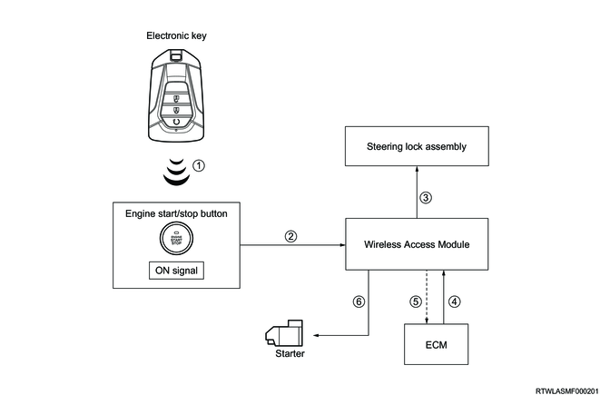
The engine is started by operating the engine start/stop button when the electronic key is in the vehicle. Unless the electronic key is authenticated by the wireless access module and ECM, the engine cannot be started.
When the engine start/stop button is pressed, the wireless access module sends radio signals from the center in-vehicle antenna to the electronic key. After receiving these radio signals, the electronic key will send radio signals to the receiver in the wireless access module. When the wireless access module receives radio signals, it starts authentication with the electronic key. When authentication is complete, the wireless access module starts authentication with the steering lock assembly. When authentication is complete, the steering wheel lock is unlocked.
The wireless access module starts authentication with the ECM and the starter ON output when the power mode is turned ON. When authentication is complete, the ECM sends the starter ON permission signal and the wireless access module starts the engine.
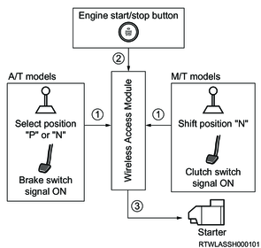
1. Engine startup condition
The engine can be started by operating the engine start/stop button for the following.
M/T models
- The shift lever is in the N position.
- Depress the clutch pedal.
- Press the engine start/stop button.
A/T models
- The selector lever is in the P or N position.
- Depress the brake pedal.
- Press the engine start/stop button.
Note
- If the steering wheel lock is not released, the engine cannot be started.
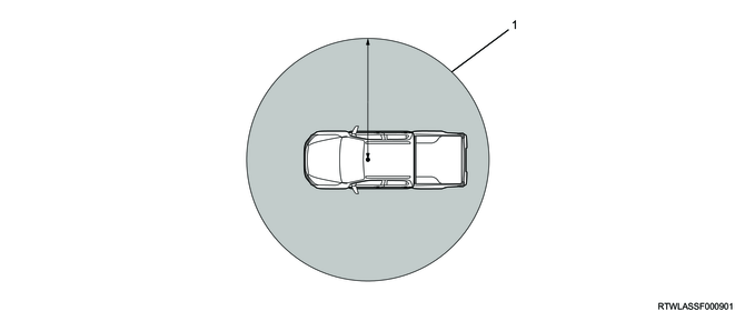
Schematic drawing of immobilizer function (passive entry and start system)

Range in which the engine can be started using immobilizer function (passive entry and start system)
Legend
- Operating range for starting the engine
2. Passive entry and start system authentication by transponder (electronic key)
If starting the engine becomes impossible for some reason (drained electronic key battery, etc.), place the electronic key with the built-in transponder near the engine start/stop button and authenticate with the wireless access module, then press the engine start/stop button to start the engine. When the engine is started using the transponder, authentication is performed between the transponder and the wireless access module, and between the wireless access module and the ECM.
6. Emergency function
1. Emergency stop function
The engine can be stopped during start-up by performing either of the following operations.
- Press and hold the engine start/stop button for 3 seconds or more.
- Press the engine start/stop button 3 times within 2 seconds.
2. Emergency starting function
The engine may be started by operating the engine start/stop button for the following.
Caution
- Ensure the safety of the surrounding area in case unexpected vehicle behavior occurs when starting the engine.
M/T models
- The power mode is set to ACC.
- The shift lever is in the N position.
- Depress the clutch pedal.
- Press and hold the engine start/stop button for 15 seconds or more.
A/T models
- The power mode is set to ACC.
- The selector lever is in the P or N position.
- Depress the brake pedal.
- Press and hold the engine start/stop button for 15 seconds or more.
Note
- After switching to ACC, operate within 5 minutes.
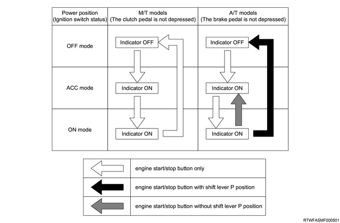
7. Power mode switching function
The mode is switched as shown in the following diagram by operating the engine start/stop button on each operation.
1. Remote engine start function (A/T models)
The remote engine start is possible by pressing the remote engine start button for 1 second within 5 seconds after operating the lock button on the electronic key within the range from approximately 20 m (approximately 66 ft) to maximum approximately 50 m (approximately 164 ft) from the center of the vehicle. Advance engine warm-up and vehicle temperature adjustment by the air conditioner can be performed for a predetermined length of time. For engine start using the remote engine start, the number and time are counted in the wireless access module. The function can be used up to 3 consecutive times including extension operation. Engine startup and extension operation are inhibited for a third time or more. The counts are reset by performing a normal engine startup, and the function can be used again. The remote engine start function operates as follows.
Note
- Because the remote engine start function does not work with other functions, operate the air conditioner switch beforehand when adjusting the temperature of the vehicle by the air conditioner.
Remote engine start conceptual diagram

1) Remote engine start button operation
The remote engine start request can be sent to the wireless access module by pressing the remote engine start button for 1 second within 5 seconds after pressing the lock button on the electronic key within the operating range of the function. When the wireless access module receives a request via a built-in receiver, it starts the precondition check.
2) Precondition check
The wireless access module verifies that the following preconditions are met before starting the engine by the remote engine start function. The remote engine start does not function when any one is outside the preconditions.
- The remote engine start function is Enable using the user customization function.
- The power mode is OFF.
- The selector lever is in the P position.
- All doors (including engine hood) are closed and placed in the lock position
- The steering wheel lock is in the lock position.
- The brake pedal is not depressed.
- The electronic key is not in the vehicle.
- The vehicle is stopped (vehicle speed 0 km/h).
Note
- If a center in-vehicle antenna malfunction or specific wireless access module malfunction is detected, the remote engine start does not function.
When 1 second has passed after the precondition was met, the external buzzer sounds once and the hazard warning light flashes once to notify the surrounding area.
3) POWER MODE ON
The wireless access module turns ON the power mode to start the engine and supplies power to each device, ECM, instrument panel cluster, etc.
At this time, the wireless access module communicates with the ECM via CAN communication to authenticate. In addition, it receives the signals such as an engine speed signal and vehicle speed signal.
4) Start the engine.
The wireless access module sends the starter ON output to start the engine for a predetermined length of time. After starting the engine, the wireless access module sounds the external buzzer 3 times and flashes the hazard warning lights 3 times to notify the surrounding area of the engine startup. "REMOTE ENGINE START MODE" is displayed on the MID in the instrument panel cluster for 2 seconds when the engine is started.
Note
- When the remote engine start is extended, press the remote engine start button for 1 second within 5 seconds after operating the lock button on the electronic key. When the wireless access module receives an extension request, it resets the counting time and continues the engine start for the set time. When it continues, the external buzzer sounds 3 times and the hazard warning lights flashes 3 times to notify that the extension operation is performed.
- The remote engine start function is the MID user customization function, and it can change the idling time after starting the engine to Min (3 minutes), Mid (5 minutes), Max (10 minutes), or Disable. (The default setting is Max (10 minutes).
The engine is stopped when the following is detected while the engine is started using the remote engine start function.
- Outside the preconditions (except power mode OFF and except no electronic key in the vehicle)
- The engine start button is pressed again (except during extension operation)
- The set time has passed.
- The engine start/stop button is pressed.
- The engine speed is more than 1500 rpm.
Note
- The engine is stopped when the center in-vehicle antenna malfunction or the specific malfunction detection by the wireless access module is detected during engine startup using the remote engine start function.
5) Engine stopped
When the set time have passed or deviated from the conditions, the wireless access module turns OFF the power mode and stops the engine.
8. Battery protection function
If 60 minutes or more have passed in ACC, the power mode is turned OFF in order to protect the battery.
Note
- For A/T models, it does not turn OFF if the selector lever is in a position other than "P".
9. Warning function
Under the following conditions, the wireless access module will issue a warning using the MID and generate a warning sound from the buzzer embedded in the instrument panel cluster and from the external buzzer.
| Warning and MID |
Buzzer pattern |
Condition |
| No electronic key |
Short repeated beeps (external buzzer) |
If locking of an unlocked door is attempted with the electronic key not within operating range for locking and unlocking the doors. |
| Short repeated beeps (in-vehicle buzzer) |
If the electronic key is carried outside the vehicle and then the doors are closed with the power mode in "ACC" or "ON". |
|
| Short repeated beeps (external buzzer) |
||
| Three repeated beeps (in-vehicle buzzer) |
If the power mode is "OFF" and the engine start/stop button is pushed with the electronic key not within operating range for starting the engine. |
|
| Steering wheel lock not released |
Three repeated beeps (in-vehicle buzzer) |
If the steering wheel lock is not released even though the engine start/stop button is pushed. (The indicator of the engine start/stop button flashes in green.) |
| Door open |
Short repeated beeps (external buzzer) |
If door locking is attempted by pressing the request switch on the door handle or the lock button on the electronic key when the doors are open. |
| Shift position (Automatic transmission model) |
Continuous beep (external buzzer) |
If the electronic key is carried outside the vehicle and then the doors are closed with the power mode in the "OFF" and the selector lever in a position other than "P". |
| Short repeated beeps (in-vehicle buzzer) |
If the selector lever is moved to a position other than "P" with the driver side door open. |
|
| Short beep (external buzzer) |
If door locking is attempted by pressing the push buttons on the driver side door handle or electronic key with the selector lever in a position other than "P". |
|
| Three repeated beeps (in-vehicle buzzer) |
If starting of the engine is attempted by pushing the engine start/stop button with the selector lever in a position other than "P" or "N". |
|
| Three repeated beeps (in-vehicle buzzer) |
If an attempt to switch the power mode from "ON" to "OFF" is made with the selector lever in a position other than "P". |
|
| Shift position (Manual transmission model) |
Three repeated beeps (in-vehicle buzzer) |
If starting of the engine is attempted by pushing the engine start/stop button with the gearshift lever in a position other than "N". |
| Accessory mode |
Short repeated beeps (in-vehicle buzzer) |
If the driver side door is opened with the power mode in "ACC". (The indicator of the engine start/stop button illuminates in amber.) |
| - |
This message appears on the display when the power mode is in "ACC". (The indicator of the engine start/stop button illuminates in amber.) |
|
| Put electronic key close to start button |
- |
This message appears on the display when the electronic key battery goes flat. (The indicator of the engine start/stop button flashes in amber.) |
| Pre glowing Please wait |
- |
Before starting the engine, the starter output inhibition signal from the ECM is received by controlling the preheating start. (Engine start/stop button indicator illuminates in amber.) |
| Turn off the power |
Short beep (external buzzer) |
If door locking is attempted by pressing the push button on the door handle or electronic key with the power mode in "ON" or "ACC". |
| Low battery Electronic key |
Three repeated beeps (in-vehicle buzzer) |
If the battery voltage of the electronic key is low when the power mode is switched from "ON" to "OFF" (or "ACC"). |
| Power management system |
Three repeated beeps (in-vehicle buzzer) |
If an error occurs to the power management system when the engine start/stop button is pushed. |
| Steering wheel lock system |
Three repeated beeps (in-vehicle buzzer) |
If an error occurs to the steering wheel lock system when the engine start/stop button is pushed. |
| Check engine hood |
Short beep (external buzzer) |
If door locking is attempted by pressing the push button on the driver side door handle or electronic key when the engine hood is open. |
| Lockout prevention (No multi-display warning) |
Short repeated beeps (external buzzer) |
If vehicle locking is attempted by pressing the push button on the driver side door handle when the electronic key is within operating range for starting the engine. |
| Key left prevention (No multi-display warning) |
Short repeated beeps (external buzzer) |
When a door handle is used to do a lock operation while the key is inside the vehicle. |
| Check system |
Three repeated beeps (in-vehicle buzzer) or Continuous beep (in-vehicle buzzer) |
If the engine start/stop button is pressed when an error occurs in the system related to the wireless access module (WAM). (A buzzer sound varies depending on the error state.) |
| Short beep (external buzzer) or Continuous beep (external buzzer) |
If door locking is attempted by pressing the push button on the driver side door handle when an error occurs in the system related to the wireless access module (WAM). (A buzzer sound varies depending on the error state.) |
10. Customize function
1. Function setting using MID
The following function settings can be changed using the MID user customization function.
| Function |
Display titles of the setting items |
The details of the function |
Display titles of the options |
Option details |
Default |
| Passive entry and start system |
Communication mode |
Communication ON/OFF used in the passive entry and start system |
Radio ON |
Passive entry and start system function ON |
O |
| Radio OFF |
Passive entry and start system function OFF *Starting the engine is possible only by the transponder authentication (holding the electronic key over the engine start/stop button) |
||||
| Walk away lock |
A function to lock the doors when the driver walks away from the vehicle with the electronic key |
Enable |
The function is ON. |
O |
|
| Disable |
The function is OFF. |
||||
| Answerback chime |
Setting of the external buzzer volume when the answer back is in operation |
Disable |
External buzzer OFF |
||
| Min |
Volume: small |
||||
| Mid |
Volume: medium |
||||
| Max |
Volume: large |
O |
|||
| Welcome light |
A function to illuminate the dome light when the driver with the electronic key approaches the vehicle |
Enable |
The function is ON. |
||
| Disable |
The function is OFF. |
O |
|||
| Walk away lock chime |
A function to sound an external buzzer when the walk away door lock does not operate normally |
Enable |
The function is ON. |
||
| Disable |
The function is OFF. |
O |
|||
| Driver door select unlock |
A function that unlocks the doors in steps |
Enable |
The function is ON. |
O |
|
| Disable |
The function is OFF. |
||||
| Remote engine start |
Remote start idle time |
Setting of idling time after engine start by remote engine start |
Disable |
The function is OFF. |
|
| Min |
3-minute idling |
||||
| Mid |
5-minute idling |
||||
| Max |
10-minute idling |
O |
11. Wireless Access Module controls components
1. Request switch
The request switch is on the outside handle. Locking/unlocking the doors using the request switch is only possible with the power mode OFF. All the doors will lock/unlock when the request switch is pressed and it has been verified that the electronic key is within the range.
2. External antenna
The external antenna is built into the outside handle. If the outside handle request switch is pressed, the external antenna sends radio signals to the electronic key.
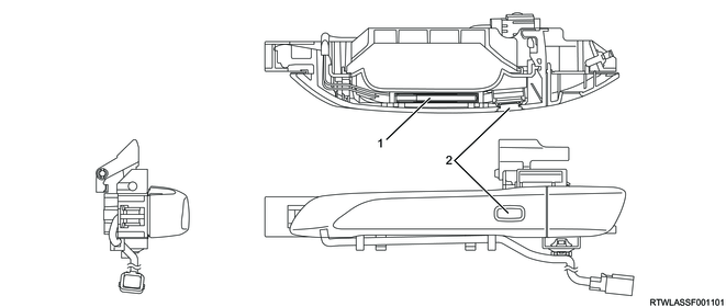
Legend
- External antenna
- Request switch
Outside handle (external antenna, request switch) connector pin layout
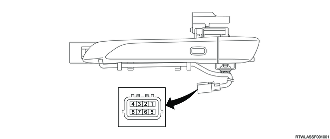
| Pin No. |
Pin Function |
Pin No. |
Pin Function |
| 1 |
External antenna (-) |
5 |
External antenna (+) |
| 2 |
- |
6 |
- |
| 3 |
- |
7 |
- |
| 4 |
Request switch signal |
8 |
Request switch ground |
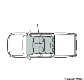
3. Center in-vehicle antenna
The center in-vehicle antenna is installed to the rear side of the center console. When the engine start/stop button is pressed, the wireless access module sends radio signals from the center in-vehicle antenna to the electronic key.
Center in-vehicle antenna
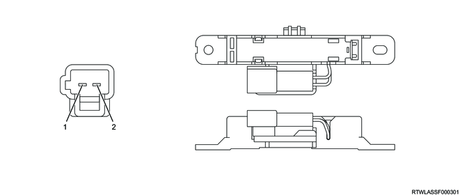
| Pin No. |
Pin Function |
| 1 |
Center in-vehicle antenna (+) |
| 2 |
Center in-vehicle antenna (-) |
4. Electronic key
By carrying the electronic key, it is possible to lock/unlock doors and start the engine without inserting a mechanical key. It is also possible to lock/unlock doors using the lock/unlock buttons on the electronic key.
If starting the engine becomes impossible for some reason (drained electronic key battery, etc.), place the electronic key with the built-in transponder near the engine start/stop button and press the engine start/stop button to start the engine. If the engine start/stop button is pressed, the engine start/stop button LED indicator will begin to flash. Place the electronic key near the engine start/stop button when the LED indicator is flashing to authenticate with the passive entry and start system, and then the buzzer will sound. After authentication, the engine is started by pressing the engine start/stop button within 10 seconds after the LED indicator starts flashing slowly. If it is not authenticated or the engine start/stop button is not pressed within 10 seconds after authentication, the LED indicator of the engine start/stop button will turn OFF. It is possible to register a maximum of 5 electronic keys. The battery life of the electronic key is approximately 2 years, though it varies depending on usage conditions.
The electronic key has a function to prevent the unauthorized communication with the vehicle. When the lock button is pressed and the unlock button is pressed and held for 5 seconds at the same time, the function will operate and the electronic key indicator flashes twice. The passive entry and start system communication is stopped when the function is operating. To cancel the function, operate any of the electronic key buttons.
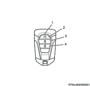
Legend
- Indicator light
- Remote engine start button
- Lock button
- Unlock button
5. Engine start/stop button, steering lock assembly
The engine start/stop button is used to switch the power mode to ACC or ON, and to start the engine. When the engine start/stop button is pressed, the wireless access module starts authentication with the electronic key. When authentication is complete normally, the wireless access module starts authentication with the steering lock assembly. When authentication is complete normally, the steering wheel lock is unlocked.
The wireless access module starts authentication with the ECM when the power mode is turned ON. When authentication is complete, the ECM sends the starter ON permission signal and the wireless access module starts the engine.
If starting the engine becomes impossible for some reason (drained electronic key battery, etc.), place the electronic key with the built-in transponder near the engine start/stop button to start authentication with the wireless access module. When authentication is complete normally, the engine can be started by pressing the engine start/stop button.
Engine start/stop button
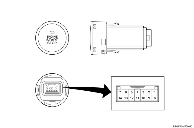
| Pin No. |
Pin Function |
Pin No. |
Pin Function |
| 1 |
- |
8 |
Immobilizer coil (-) |
| 2 |
Engine start/stop switch 2 signal |
9 |
Immobilizer coil (+) |
| 3 |
- |
10 |
- |
| 4 |
Engine start/stop switch 2 ground |
11 |
Engine start/stop button illumination |
| 5 |
Engine start/stop switch 1 / LED ground |
12 |
Engine start/stop button LED indicator (green) |
| 6 |
- |
13 |
Engine start/stop button LED indicator (amber) |
| 7 |
Engine start/stop switch 1 signal |
14 |
- |
Steering lock assembly
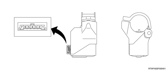
| Pin No. |
Pin Function |
| 1 |
Ground |
| 2 |
- |
| 3 |
Steering lock operating permission signal |
| 4 |
Steering lock position signal |
| 5 |
LIN communication |
| 6 |
Ignition power supply |
| 7 |
Battery power supply |
6. External buzzer
The external buzzer is installed in the engine room. External buzzer (answerback buzzer) operation/non-operation and volume settings can be changed with the user customization function on the MID or the scan tool. The external buzzer also has the function of a warning buzzer and will generate a warning sound when the key monitor warning light performs a warning.
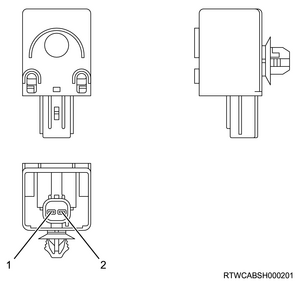
| Pin No. |
Pin Function |
| 1 |
Ground |
| 2 |
External buzzer control |
7. Key monitor warning light
If a malfunction occurs in the wireless access module, the key monitor warning light illuminates or blinks to inform the driver of a malfunction in the system.
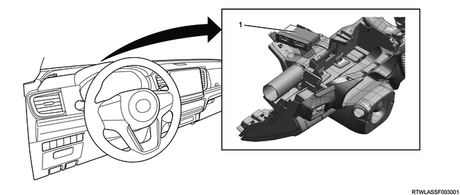
12. Wireless Access Module controls component views
The passive entry and start system consists of the following parts.
Note
- The illustration shows a crew cab model.
RHD
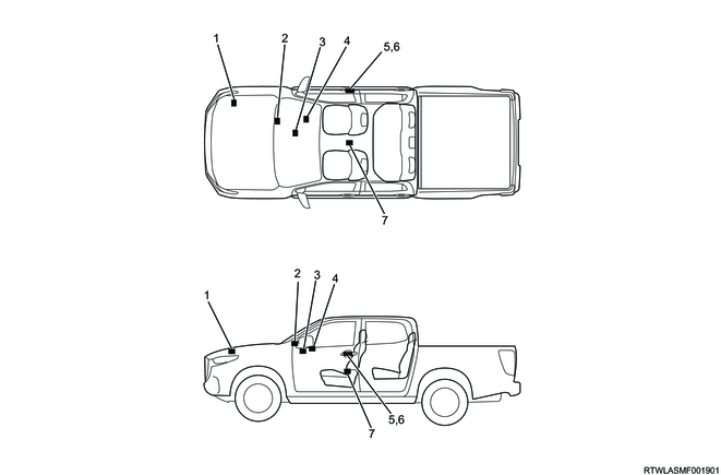
Legend
- External buzzer
- Wireless access module
- Engine start/stop button
- Steering lock assembly
- Request switch
- External antenna
- Center in-vehicle antenna
LHD
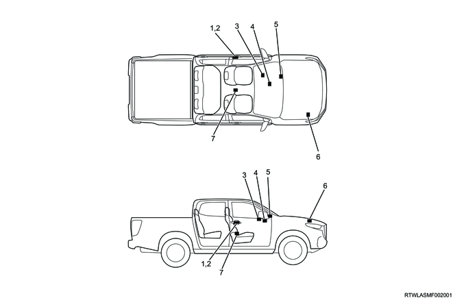
Legend
- Request switch
- External antenna
- Steering lock assembly
- Engine start/stop button
- Wireless access module
- External buzzer
- Center in-vehicle antenna
RHD
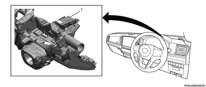
Legend
- Wireless access module
LHD
Legend
- Wireless access module
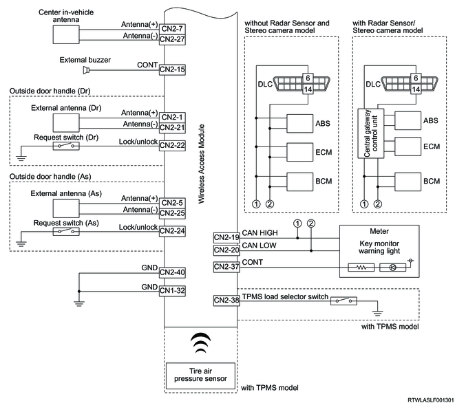
13. General circuit diagram
1. Wireless access module (Hi-version) general circuit diagram
1/2

2/2
2. Wireless access module (Hi-version) appearance, connector pin layout diagram

| PIN No. |
Pin Function |
| 1 |
Battery power supply |
| 2 |
- |
| 3 |
IG1 relay control |
| 4 |
- |
| 5 |
IG2 relay control |
| 6 |
ACC relay control |
| 7 |
Starter relay control |
| 8 |
Clutch output signal (M/T) |
| 9 |
Engine start/stop button LED indicator (amber) |
| 10 |
Engine start/stop button LED indicator (green) |
| 11 |
Engine start/stop button illumination |
| 12 |
Clutch input signal (M/T) |
| 13 |
Vehicle speed signal |
| 14 |
Immobilizer coil (+) |
| 15 |
Immobilizer coil (-) |
| 16 |
- |
| 17 |
- |
| 18 |
- |
| 19 |
IG1 feedback signal |
| 20 |
- |
| 21 |
IG2 feedback signal |
| 22 |
ACC feedback signal |
| 23 |
- |
| 24 |
Parking switch signal (A/T) |
| 25 |
- |
| 26 |
Engine start/stop switch 1 signal |
| 27 |
Engine start/stop switch 2 signal |
| 28 |
P/N position switch signal (A/T) / Neutral switch signal (M/T) |
| 29 |
- |
| 30 |
Stoplight switch signal |
| 31 |
- |
| 32 |
Power ground |
| PIN No. |
Pin Function |
| 1 |
External antenna (+) (Driver door) |
| 2 |
- |
| 3 |
- |
| 4 |
- |
| 5 |
External antenna (+) (passenger door) |
| 6 |
- |
| 7 |
Center in-vehicle antenna (+) |
| 8 |
- |
| 9 |
- |
| 10 |
- |
| 11 |
- |
| 12 |
- |
| 13 |
- |
| 14 |
Steering lock inhibition |
| 15 |
External buzzer control |
| 16 |
Steering lock position signal |
| 17 |
Steering lock operating permission signal |
| 18 |
LIN communication |
| 19 |
CAN high signal |
| 20 |
CAN low signal |
| 21 |
External antenna (-) (Driver door) |
| 22 |
Request switch signal (Driver door) |
| 23 |
- |
| 24 |
Request switch signal (passenger door) |
| 25 |
External antenna (-) (passenger door) |
| 26 |
- |
| 27 |
Center in-vehicle antenna (-) |
| 28 |
- |
| 29 |
- |
| 30 |
- |
| 31 |
- |
| 32 |
- |
| 33 |
- |
| 34 |
- |
| 35 |
- |
| 36 |
- |
| 37 |
Key monitor warning light control |
| 38 |
TPMS load selector switch |
| 39 |
- |
| 40 |
Signal ground |