1. Maintenance precautions of lighting control
Caution
- The bulb becomes hot when illuminated, so if the bulb surface is stained with grease, etc., the life of the bulb will be shortened. Hold the flange section when replacing the bulb, and do not touch the glass section directly.
- The pressure inside the glass bulb is high. Broken glass may fly everywhere if it is dropped, hit, or damaged.
- If left for an extended period of time with the bulb removed, dust or moisture may enter the lens. Prepare a new bulb before replacing the bulb.
- Be sure to use a bulb with the same wattage for replacement.
- Improper installation of the socket may cause foggy lens or water intrusion, so securely install it after replacing the bulb.
1. Using circuit test tools
Unless instructed in the diagnostic procedure, do not use a test lamp. When a probe connector is required in a diagnostic procedure, use connector test adapter kit (5-8840-2835-0).
2. Commercial electronic equipment
Aftermarket electronic equipment refers to commercially available electronic equipment installed to the vehicle after it has been shipped from the factory. Be careful, as such accessories are not taken into particular consideration at the vehicle design stage.
Aftermarket electronic equipment may cause malfunctions in the electronic control system, even if the equipment is properly installed. Aftermarket electronic equipment includes devices not connected to the electronic control system of the vehicle, such as mobile phones or radios. Therefore, when diagnosing electrical system problems, first check whether such aftermarket electronic equipment is installed. Remove it from the vehicle if installed. If the problem has not been resolved after removing the equipment, perform the diagnosis using the regular procedure.
Caution
- Make sure that both the power supply and ground of aftermarket electronic equipment are connected to a circuit that is not related to the circuits of the electronic control system.
3. Damage caused by static electricity
Because the electronic components used in the electronic control system are designed to operate at extremely low voltages, they can be easily damaged by static electricity, and some types of electronic components can be damaged by static electricity of 100 V or less, which cannot be felt by a person. (A voltage of 4,000 V is required for a person to be able to detect a static electricity.)
There are various ways a person can build up an electrostatic charge. The most common way to build up an electrostatic charge is through friction or induction. An example of when a person builds an electrostatic charge by friction is when they slide across the seat of the vehicle. A person wearing insulated shoes can build an electrostatic charge by induction if they momentarily touch the ground while standing near a highly charged object. A charge of the same polarity flows out, and with a highly opposing polarity, that person becomes charged. Because static electricity can be damaging, be extremely careful when handling or testing electronic components.
Caution
- To prevent damage caused by static electricity, do not touch the connector pins of the headlight auto leveling control unit or the electronic components soldered onto the circuit board of the headlight auto leveling control unit.
- To prevent damage caused by static electricity, do not open the packaging of a replacement part until the preparations for installation of the part are completed.
- To prevent damage caused by static electricity, connect the package to a properly working vehicle ground before removing the part from the package.
- To prevent damage caused by static electricity, touch a properly working ground before installing the part in such cases as when handling the part while sliding across a seat, when sitting down from a standing position, or while walking a certain distance.
4. Tools to be used
When measuring the voltage and resistance, make sure to correctly use the tools, such as the scan tool, connector test adapter kit (5-8840-2835-0), and digital multimeter [DMM] (5-8840-0285-3).
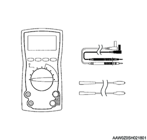
5. Digital multimeter (DMM)
Use the specified DMM (5-8840-0285-3) for diagnosing or repairing the headlight auto leveling control unit. Use of another DMM for diagnosing or repairing the headlight auto leveling control unit is not allowed.
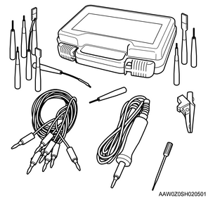
6. Connector test adapter kit
Use the connector test adapter kit (5-8840-2835-0) when the diagnostic procedure requires inspection or detailed checking using a terminal. Use the appropriate adapter to prevent the terminal from being damaged.