1. Headlight auto leveling system overview
The headlight auto leveling system automatically adjusts the optical axis of the headlights in accordance with the change of the vehicle posture. The headlight auto leveling system consists of the following parts.
- Headlight auto leveling control unit
- G sensor
- Headlight leveling actuator
- Headlight automatic leveling warning light
Headlight auto leveling system schematic
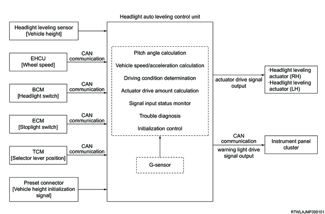
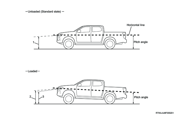
Based on the vehicle speed signals, headlight switch signals, and headlight leveling sensor signals, the headlight auto leveling control unit performs optical axis control according to the vehicle conditions. If the vehicle posture is changed, the headlight auto leveling control unit compares the pitch angle calculated from the headlight leveling sensor signals and the specified pitch angle stored in advance. The headlight auto leveling control unit drives the headlight leveling actuators and adjusts the optical axis to offset the difference between the compared 2 pitch angles.
Legend
- Initial aiming angle
- Optical axis before leveling control
- Optical axis after leveling control
2. Headlight auto leveling system
The headlight auto leveling control unit performs the following controls.
- Basic control
- Additional control
- Fail-safe control
1. Basic control
The basic control performs 4 controls based on vehicle speed and headlight switch signals.
- Headlight ON control while stopped
- Headlight ON control while driving
- Control while stopped
- Driving control
1) Headlight ON control while stopped
The control is performed when the headlight switch is turned from OFF to ON while the vehicle is stopped. The headlight leveling actuators are driven to control the optical axis based on the average pitch angle for the 1 second immediately before the headlight switch is turned ON.
2) Headlight ON control while driving
The control is performed when the headlight switch is turned from OFF to ON while the vehicle is running. The headlight leveling actuators are driven to control the optical axis based on the average pitch angle for the 1 second immediately before the headlight switch is turned ON.
3) Control while stopped
The control is performed when it is detected that the vehicle posture is stable for 3 seconds or more after the vehicle is stopped from the running state with the headlight switch ON.
4) Driving control
The control is performed when it is detected that the vehicle is running at a fixed speed (within the range of 30 km/h {19 mph} or more, less than 180 km/h {112 mph}) with the headlight switch ON for 3 seconds or more.
Note
- Driving control is performed only once for 1 driving.
2. Additional control
Detect and verify for the following in order to perform driving control accurately.
- Rough road detection
- Certainty verification
1) Rough road detection
If the headlight auto leveling control unit detects a change in the headlight leveling sensor signals while determining driving control (within 3 seconds), it determines rough road and suspends driving control.
Note
- If the conditions for driving control are met again, driving control is performed.
2) Certainty verification
After driving control is completed, if the data used for the control is determined to be incorrect, the headlight auto leveling control unit replaces it with a pitch angle that is determined to be correct (average for 3 seconds), and then drives the headlight leveling actuators again to control the optical axis.
Note
- Certainty verification is performed only once for 1 driving.
3. Fail-safe control
If a headlight auto leveling system malfunction is detected, the headlight auto leveling control unit stops the headlight leveling actuator drive. The headlight auto leveling control unit illuminates or flashes the headlight automatic leveling warning light in the instrument panel cluster.
3. Headlight auto leveling system components
1. Headlight auto leveling control unit
The headlight auto leveling control unit is installed in the driver-side instrument panel. Based on various signals and the G sensor signals received via CAN communication, the headlight auto leveling control unit performs optical axis control according to the vehicle conditions.

2. Headlight leveling actuator
The headlight leveling actuators are installed to the left and right headlights and have built-in motors. The motors operate in accordance with control voltage supplied from the headlight auto leveling control unit to change the optical axis of the headlights. If the headlight auto leveling control unit determines that optical axis adjustment is required based on headlight leveling sensor signals, a control signal is output to the headlight leveling actuators.
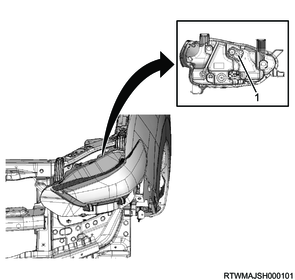
Legend
- Headlight leveling actuator
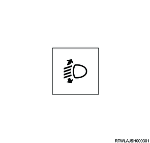
3. Headlight automatic leveling warning light
The headlight automatic leveling warning light is in the instrument panel cluster. The headlight automatic leveling warning light illuminates for approx. 3 seconds when the ignition switch is turned ON, and then turns OFF. If the headlight auto leveling system malfunction is detected, the headlight automatic leveling warning light illuminates or flashes. Also, if the initialization of the vehicle height values is performed, the headlight automatic leveling warning light flashes.
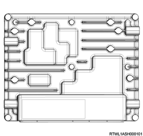
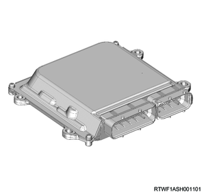
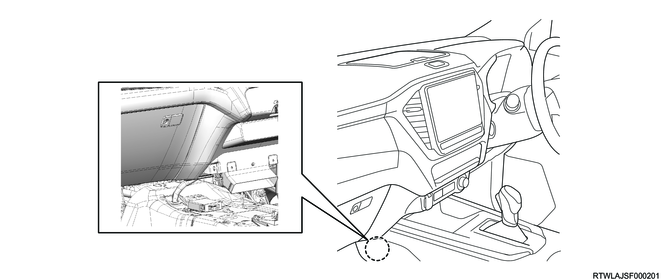
4. ECM
The ECM is installed inside the passenger-side instrument panel. The ECM sends the stoplight switch signals to the headlight auto leveling control unit via the CAN communication circuit.
4JJ3 engine models
RZ4E-TC engine models
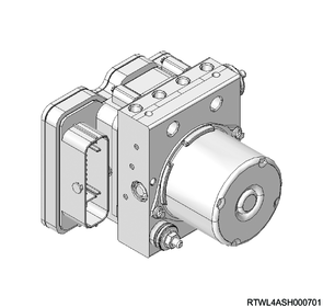
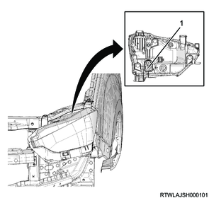
5. EHCU
The EHCU is installed in the engine room. The EHCU sends the wheel speed signals to the headlight auto leveling control unit via the CAN communication circuit.
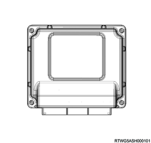
6. TCM
The TCM is installed inside the passenger-side instrument panel. The TCM sends the select lever position signals to the headlight auto leveling control unit via the CAN communication circuit.
7. BCM
The BCM is installed to the driver-side dash side panel. The BCM sends the headlight switch signals to the headlight auto leveling control unit via the CAN communication circuit.
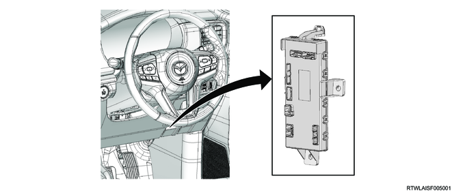
4. Headlight auto leveling system component views
Note
- The illustration shows an RHD model.
Legend
- Headlight auto leveling control unit
Legend
- Headlight leveling actuator
Note
- The illustration shows an RHD model.

Legend
- ECM
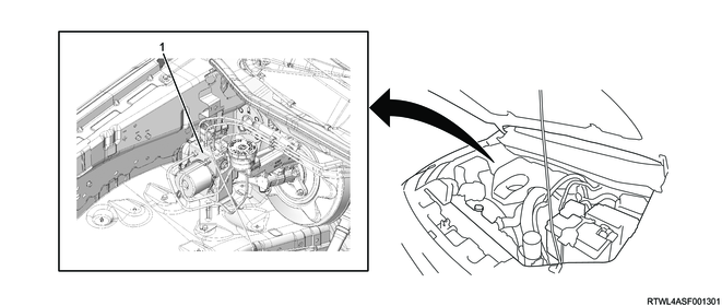
Legend
- EHCU
Note
- The illustration shows an RHD model.

Legend
- TCM
Note
- The illustration shows an RHD model.
Legend
- BCM
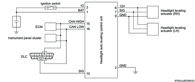
5. General circuit diagram
1. Headlight auto leveling control unit general circuit diagram
2. Headlight auto leveling control unit outline view and connector pin layout
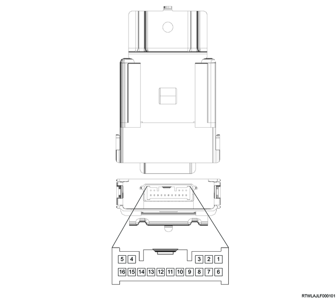
| No. |
Pin Function |
| 1 |
Battery voltage |
| 2 |
Ground |
| 3 |
Ignition voltage |
| 4 |
- |
| 5 |
- |
| 6 |
Headlight leveling actuator (RH) and Headlight leveling actuator (LH) 12V reference |
| 7 |
Headlight leveling actuator (RH) and Headlight leveling actuator (LH) ground |
| 8 |
- |
| 9 |
Headlight leveling actuator (RH) and Headlight leveling actuator (LH) signal |
| 10 |
Initialization signal |
| 11 |
- |
| 12 |
- |
| 13 |
- |
| 14 |
- |
| 15 |
CAN high signal |
| 16 |
CAN low signal |