1. Parking aid system overview
The parking aid system is a device that measures the distance from an object around the vehicle by the sonar sensor, which generates the ultrasonic waves, to alert the driver according to the distance from the object. A buzzer sounded from the instrument panel cluster and indication on the multi-information display alert the driver. This device is activated when the vehicle speed is approx. 10 km/h {6 mph} or less.
Warning
- The parking aid system is not a system that assists in the driving operation to automatically avoid collision or stops the vehicle safely. It is necessary not to overly trust the system but to keep in mind safe driving.
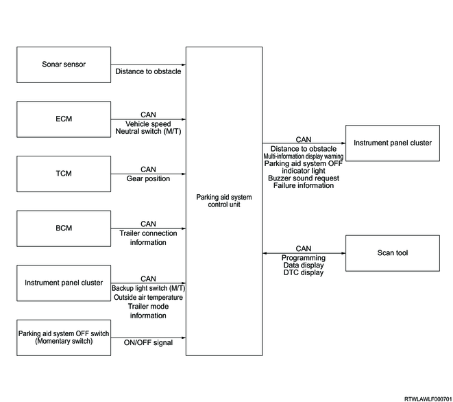
Parking aid system control unit input/output diagram
2. Parking aid system
1. System activation
The parking aid system OFF indicator light and master warning light illuminate when the ignition switch is turned ON. They turn OFF after approximately 3 seconds if the system is normal.
Parking aid system OFF indicator light

Master warning light
2. System operation setting
The operation of the parking aid system OFF switch can set ON/OFF of the system. The parking aid system OFF indicator light in the instrument panel cluster illuminates if the system is deactivated. Even if the engine is stopped with the system deactivated, the system will always be in an operating condition when the engine is restarted.
Parking aid system OFF switch
3. Operating system conditions
The parking aid system is activated when all the following conditions are met.
1) The vehicle moves backward.
- The ignition switch is in the ON position.
- The parking aid system OFF switch is not pressed.
- The vehicle speed is approx. 10 km/h {6 mph} or less.
- The shift lever is in the R position.
2) The vehicle runs forward (Models with front sonar sensors)
- The ignition switch is in the ON position.
- The parking aid system OFF switch is not pressed.
- The vehicle speed is approx. 10 km/h {6 mph} or less.
- The shift lever is in a position other than the neutral position (manual transmission models).
- The shift lever is in the D or R position (automatic transmission models).
4. Conditions where the system does not operate normally
The system may not operate normally under the following conditions.
- The temperature around the sonar sensor is extremely high or low.
- The sonar sensor is frozen.
- A large amount of water splashes on the sonar sensor due to heavy rain, etc.
- Water splashes to the sonar sensor when running on a flooded road.
- The vehicle posture changes significantly.
- Objects or walls are around the vehicle in a narrow tunnel, narrow bridge, narrow road, small garage, etc.
- There is a steep slope in the direction of travel.
- There is a curb in the direction of travel.
- The vehicle is running on an uneven road.
- Mud, snow, ice, or other similar matters are on or around the sonar sensor.
- The sonar sensor body or the area around the sonar sensor is blocked.
- The position or orientation of the sonar sensor is deviated due to a collision, etc.
- The vehicle is running on a gravel road, rough road, in the grass, etc.
- Other vehicles which generate a high frequency sound (horn, motorcycle engine sound, air brake noise of a large vehicle, a device such as sonar sensor that generates ultrasonic waves, etc.) are close to the vehicle.
- An aftermarket fender pole or radio antenna is installed.
- An obstacle is too close to the sonar sensor.
5. Sonar sensor operation range
The sonar sensor detects an obstacle in the following range.
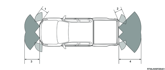
Legend
- Approx. 60 cm (Front outer sonar sensor)
- Approx. 60 cm (Rear outer sonar sensor)
- Approx. 100 cm (Front inner sonar sensor)
- Approx. 150 cm (Rear inner sonar sensor)
6. Sonar sensor detection performance
The sonar sensor may not detect the following objects as obstacles.
- Pedestrian
- Moving object such as a vehicle and animal
- An object just under the bumper
- Thin or low object
- A threadlike object such as a wire, fence, and rope
- An object such as snow, clothes, and sponge whose material easily absorbs sound
- Sharp object
- An object having a sloping surface.
- A suspended object or an object placed at a high position.
- An object existed around the sonar sensor before the system is activated
7. Multi-information display and buzzer
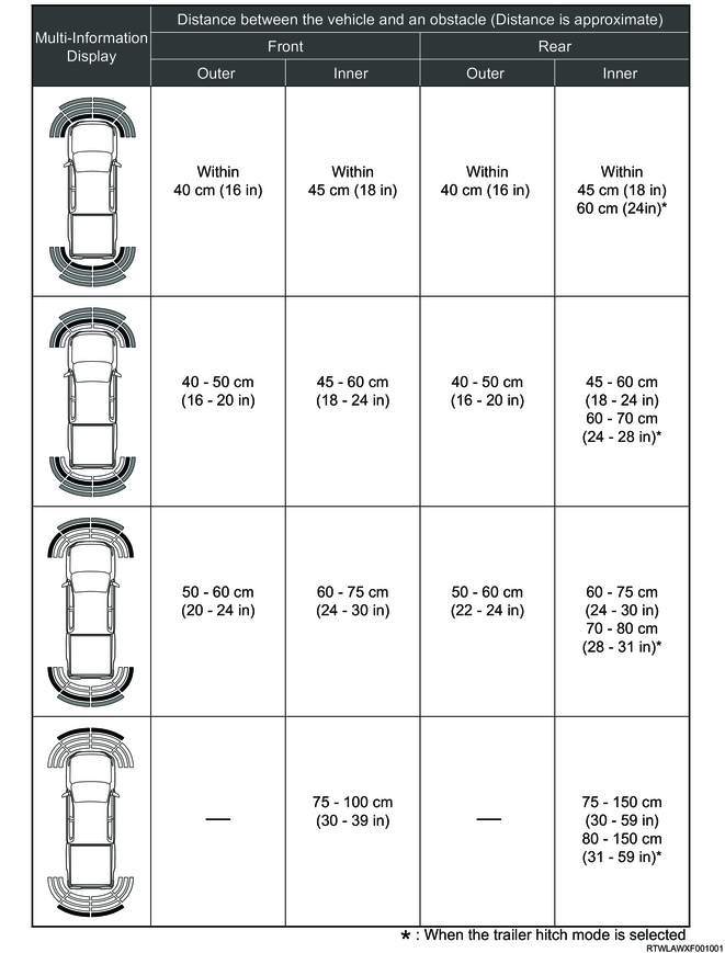
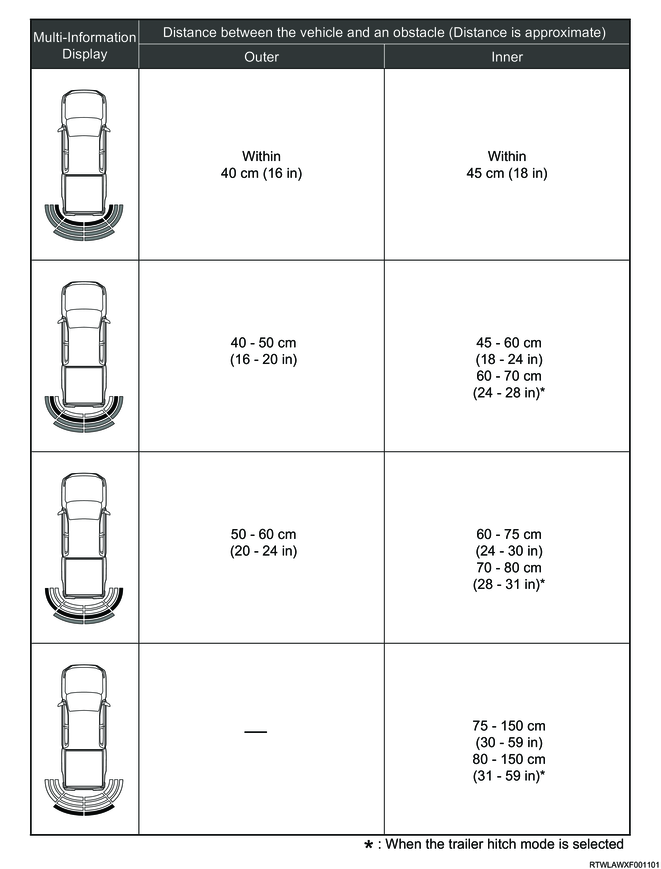
1) Multi-information display
The obstacle detection status is displayed on the multi-information display. When the sonar sensor detects an obstacle, the corresponding area turns red. The following indications are displayed on the multi-information display depending on the distance between the vehicle and an obstacle.
Models with front sonar sensors
Except models with front sonar sensors
2) Buzzer
The buzzer sounds are distinguished by 4 levels according to the distance from an obstacle. The following alarm sounds from the instrument panel cluster according to the distance between the vehicle and an obstacle.
| Buzzer sound |
Distance between the vehicle and an obstacle |
|||
| Front |
Rear |
|||
| Outer |
Inner |
Outer |
Inner |
|
| Continuous beeps |
Within approx. 40 cm |
Within approx. 45 cm |
Within approx. 40 cm |
Within approx. 45 cm |
| Within approx. 60 cm* |
||||
| Intermittent sound |
Approx. 40 to 50 cm |
Approx. 45 to 60 cm |
Approx. 40 to 50 cm |
Approx. 45 to 60 cm |
| Approx. 60 to 70 cm* |
||||
| Intermittent sound |
Approx. 50 to 60 cm |
Approx. 60 to 75 cm |
Approx. 50 to 60 cm |
Approx. 60 to 75 cm |
| Approx. 70 to 80 cm* |
||||
| Intermittent sound |
- |
Approx. 75 to 100 cm |
- |
Approx. 75 to 150 cm |
| Approx. 80 to 150 cm* |
||||
| *: When the trailer hitch mode is selected. |
||||
Note
- If the multiple sonar sensors detect an object at the same time, the buzzer in the nearest position from the object makes sound.
8. Customization function
The setting of the parking aid system can be changed by the user customization function in the multi-information display. The setting value can be changed by operating the MID mode switch.
MID mode switch
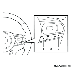
Legend
- MID mode L switch
- MID mode confirm switch
- MID mode R switch
Multi-Information Display
| Screen display |
Description |
||
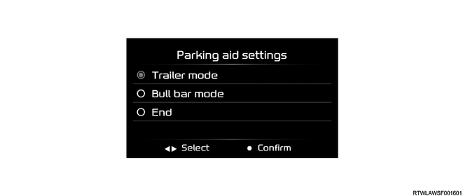
| Parking aid settings |
Trailer mode |
Off |
Cancellation of the trailer mode |
| Trailer hitch only |
Select when the trailer hitch is installed but the trailer is not installed. If this mode is selected, the distance from an obstacle detected by the rear inner sonar sensor is changed. |
||
| Bull bar mode |
Without bull bar |
Cancellation of the bull bar mode |
|
| With bull bar |
Select when a non-genuine Isuzu bull bar or bumper is installed. If this mode is selected, all the front side sonar sensors do not detect obstacles. |
||
| Note: Use the genuine Isuzu trailer hitch and harness when towing trailers. If a genuine Isuzu trailer hitch and harness are used, the setting using the user customization function is not required because the mode automatically switches to Trailer hitch only when a trailer is connected or disconnected. |
|||
| Note: If a genuine Isuzu bull bar or bumper is installed, select Without bull bar because all the front side sonar sensors can detect obstacles. |
|||
Note
- Use the user customization function with the vehicle stopped. When running the vehicle during operation, the set value is reset.
3. Parking aid system controls components
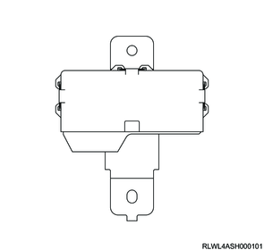
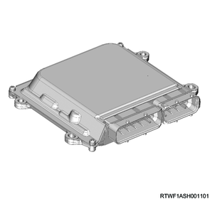
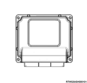
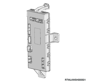
1. Parking aid system control unit
The parking aid system control unit is installed to the dash side panel on the passenger side. The parking aid system control unit determines the distance from an obstacle based on the signals received from the sonar sensors. According to the distance from the obstacle determined by the parking aid system control unit, the multi-information display changes and the instrument panel cluster buzzer sounds to alert the driver.
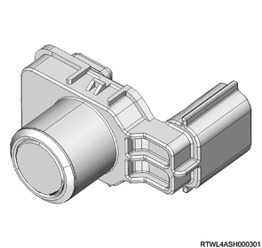
2. Sonar sensor
The rear bumper and front bumper (models with front sonar sensors) have 4 sonar sensors each. The sonar sensor measures the distance from an obstacle and sends it to the parking aid system control unit.
3. Parking aid system OFF switch
The parking aid system OFF switch is installed to the center console. When the parking aid OFF switch is pressed, the parking aid system operation can be stopped. Also, when the parking aid system OFF switch is pressed, the parking aid system OFF indicator light in the instrument panel cluster illuminates. When the parking aid system OFF switch is pressed again, the parking aid system resumes and the parking aid system OFF indicator light turns OFF.
Note
- Even if the engine is stopped with the system stopped, the system will be in an operating condition whenever the engine is restarted.
4. Parking aid system OFF indicator light
When the parking aid system is deactivated by the parking aid system OFF switch, the parking aid system OFF indicator light illuminates. Also, if a malfunction occurs in the parking aid system, the parking aid system OFF indicator light illuminates.
5. Master warning light
The master warning light illuminates when the related system malfunctions. If a malfunction occurs in the parking aid system, the master warning light and parking aid system OFF indicator light illuminate.
6. ECM
The ECM sends the vehicle speed signals, neutral switch signals, etc., to the parking aid system control unit via the CAN communication circuit.
4JJ3 engine models
RZ4E-TC engine models
7. TCM
The TCM sends the gear position, etc., to the parking aid system control unit via the CAN communication circuit.
8. BCM
The BCM sends the trailer connection information, etc., to the parking aid system control unit via the CAN communication circuit.
9. Instrument panel cluster
The instrument panel cluster sends the backup light switch signal, outside air temperature, trailer mode information, etc., to the parking aid system control unit via the CAN communication circuit. If a malfunction occurs in the parking aid system, the parking aid system OFF indicator light and master warning light are illuminated, and the following warnings are displayed on the multi-information display.
1) Sonar failure
If a malfunction occurs in the parking aid system, "Sonar failure" is displayed on the multi-information display for approximately 5 seconds.

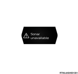
2) Sonar unavailable
If adherence of foreign material to the sonar sensor, noise, etc., is detected, "Sonar unavailable" is displayed on the multi-information display for 5 seconds.
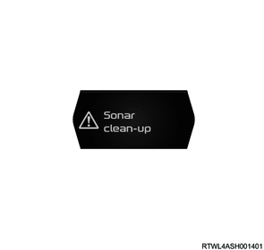
3) Sonar clean-up
If any dirt is found in the sonar sensor, "Sonar clean-up" is displayed on the multi-information display for approximately 5 seconds.
Note
- If any of "Sonar failure", "Sonar clean-up", or "Sonar unavailable" is displayed on the multi-information display, the parking aid system does not operate.
4. Parking aid system controls component views
Note
- The illustration shows an RHD model.

Legend
- Parking aid system control unit
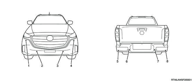
Legend
- Front outer right sonar sensor
- Front inner right sonar sensor
- Front inner left sonar sensor
- Front outer left sonar sensor
- Rear outer left sonar sensor
- Rear inner left sonar sensor
- Rear inner right sonar sensor
- Rear outer right sonar sensor
RHD models

Legend
- Parking aid system OFF switch
- Hill descent control switch
- Rear differential lock switch
LHD models
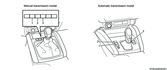
Legend
- Rear differential lock switch
- Hill descent control switch
- Parking aid system OFF switch
5. General circuit diagram
1. Parking aid system control unit general circuit diagram

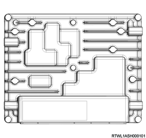
2. Parking aid system control unit overview and connector face
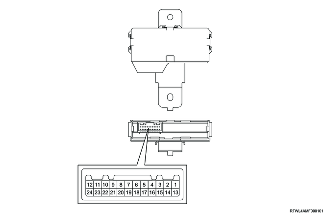
| Pin No. |
Pin function |
| 1 |
Front inner right sonar sensor signal |
| 2 |
Front inner left sonar sensor signal |
| 3 |
Front outer left sonar sensor signal |
| 4 |
Front outer right sonar sensor signal |
| 5 |
CAN (High) |
| 6 |
CAN (Low) |
| 7 |
- |
| 8 |
- |
| 9 |
Rear inner right sonar sensor signal |
| 10 |
Rear outer right sonar sensor signal |
| 11 |
Front sonar sensor power supply (12 volts reference) |
| 12 |
Ignition power supply |
| 13 |
Front sonar sensor power GND (low reference) |
| 14 |
Rear sonar sensor power GND (low reference) |
| 15 |
Ground |
| 16 |
Parking aid system OFF switch |
| 17 |
- |
| 18 |
- |
| 19 |
- |
| 20 |
- |
| 21 |
Rear inner left sonar sensor signal |
| 22 |
Rear outer left sonar sensor signal |
| 23 |
Rear sonar sensor power supply (12 volts reference) |
| 24 |
- |