1. Radar sensor system overview
1. Blind spot monitor (BSM) overview
The blind spot monitor (BSM) determines the distance between a vehicle behind and the own vehicle using a radar sensor when changing the lane. Based on this information and the own vehicle information (vehicle speed, yaw rate, turn signal, etc.), it alerts the driver of a vehicle behind getting close or a vehicle running in a blind spot. The alert to the driver is performed by the illumination or flashing of the blind spot indicators in the right and left outside rearview mirrors.
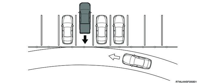
2. Rear cross traffic alert (RCTA) overview
The rear cross traffic alert (RCTA) is a function to alert the driver if a radar sensor detects a vehicle getting close from behind when starting to move backward from a parked state. The driver is alerted by flashing the blind spot indicator in the right or left outside rearview mirror and sounding the instrument panel cluster alarm.
3. System structure
The following 2 functions are integrated in the radar sensor system.
1) Blind spot monitor (BSM)
A function that informs the driver of the presence of vehicles approaching from behind and vehicles behind running in a blind spot when running on a multi-lane road, and it warns the driver of a risk of minor collision when changing the lane
2) Rear cross traffic alert (RCTA)
A function that informs the driver of the presence of vehicles approaching from behind and warns that there is a risk of minor collision when starting to move backward from the parking lot.
Warning
- The purpose of the blind spot monitor (BSM) is to assist driving operation when the lave change is performed. This device does not aid driving without looking behind carefully. It is necessary not to overly trust the system but to keep in mind safe driving.
- The purpose of the rear cross traffic alert (RCTA) is to aid the driving operation when starting to move backward. This device does not aid driving without looking behind carefully. It is necessary not to overly trust the system but to keep in mind safe driving.
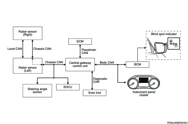
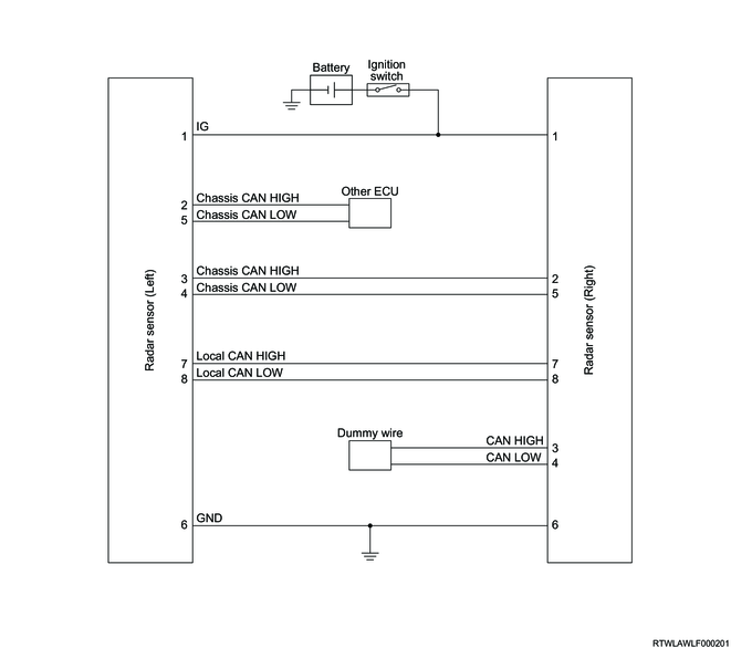
System schematic
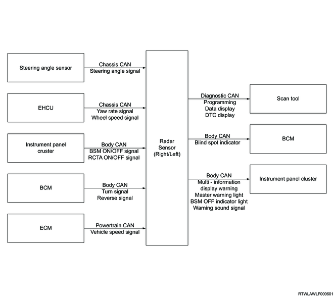
Radar sensor input/output diagram
2. Blind spot monitor (BSM)
1. System activation
When the power mode (models with passive entry and start system) or the ignition switch (except models with passive entry and start system) is turned ON, the blind spot monitor (BSM) function is turned ON.
2. System OFF setting
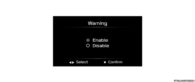
Using the MID mode switch of the steering wheel, the blind spot monitor (BSM) function can be OFF by selecting Disable from the multi-information display settings in the instrument panel.
Note
- The blind spot monitor (BSM) function is always reset to Enabled (ON) every time the ignition switch is turned ON.
- when towing another vehicle, turn OFF the blind spot monitor (BSM) function. when towing another vehicle, the blind spot monitor (BSM) may not function normally because the radar wave irradiation cannot be performed.
MID mode switch
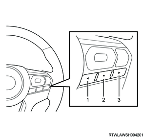
Legend
- MID mode L switch
- MID mode confirm switch
- MID mode R switch
Multi-Information Display
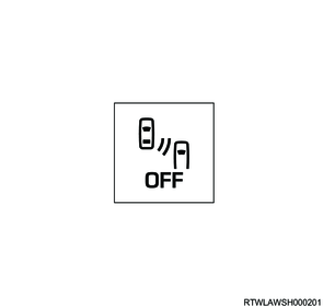
The BSM OFF indicator light in the instrument panel cluster illuminates while the blind spot monitor (BSM) function is set to Disable (OFF).
BSM OFF indicator light
3. System operation
If a vehicle behind runs within the detection range of the radar sensor while the own vehicle is running at the predetermined speed or higher, or if the radar sensor determines that the own vehicle may collide with a vehicle behind, the blind spot indicator, which is on the outside rear view mirror on the lane side where a vehicle behind is detected, illuminates or flashes. The warning by the blind spot monitor (BSM) is divided into two steps, the first warning performed when detecting a vehicle behind and the second warning performed when the driver is trying to change lanes.
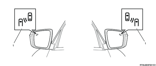
Legend
- Blind spot indicator
1) Blind spot monitor (BSM) operating conditions
It operates if all the following conditions are met.
- The Power mode (models with passive entry and start system) or the ignition switch (except models with passive entry and start system) is turned ON.
- The blind spot monitor (BSM) function is ON.
- The vehicle speed is 15 km/h {9 mph} or more.
- The shift lever or selector lever is in a position other than the R position.
2) 1st warning
When a vehicle running on the right or left adjacent lane is detected in the range of maximum 55 m from the rear step bumper while running at a vehicle speed of 15 km/h {9 mph} or more, the outside rearview mirror blind spot indicator on the lane side where the vehicle is detected illuminates.
Note
- When 2 vehicles are getting close to the own vehicle from rear right and left lanes at the same time, both blind spot indicators of the right and left outside rearview mirrors illuminate.
- When the lane is narrow and the vehicle behind is running in the outer lane, a vehicle two lanes away may be detected.
3) 2nd warning
If the driver operates the turn signal switch to the lane side in order to change the lane where the rear vehicle is detected while the first warning is in operation, the blind spot indicator of the outside rearview mirror on the lane side where the turn signal switch is operated flashes.
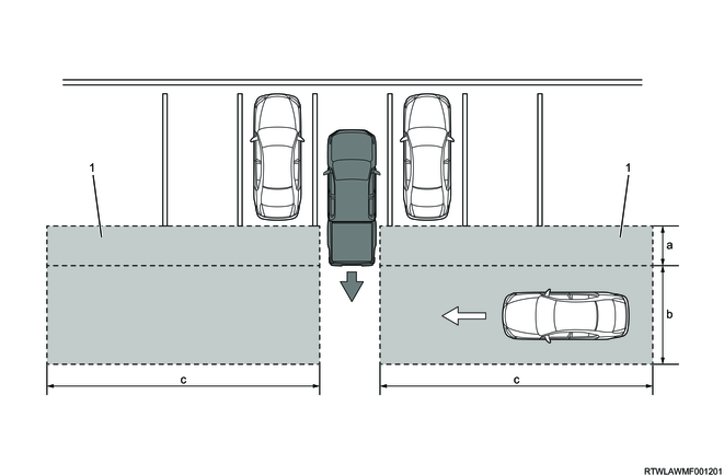
4) Detection range
The detection range of vehicles behind for the blind spot monitor (BSM) function can be divided into the following two.
Area A
- A range where vehicles running in the driver's blind spot can be detected, 1 m {3 ft} from the rear bumper in the forward direction and 7 m {22 ft} from it in the rearward direction
Area B
- A range where a rapidly approaching vehicle can be detected from 7 m {22 ft} to maximum 55 m {180 ft} from the rear step bumper.
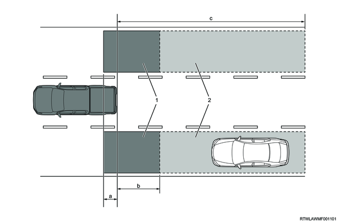
Legend
- Area A
- Area B
Detection range
a: 1.0 m { 3.3 ft }
b: 7.0 m { 23.0 ft }
c: 55.0 m { 180.4 ft }
Note
- As the speed difference between the vehicle speed of a vehicle running behind and the own vehicle speed is larger, the distance at which the blind spot indicator alarm is started is longer.
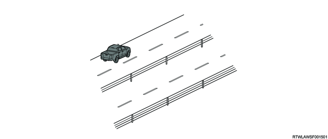
5) Auto alignment function
The auto alignment is a function that automatically corrects the deviation of the vehicle detection range of the radar sensor within a range of ±7.4° while running. Deviations in the vehicle detection range of the radar sensor occur due to improper installation, damage, etc., of the radar sensor and peripheral parts of the radar sensor (such as the radar sensor bracket and rear step bumper). Therefore, the radar sensor corrects the vehicle detection range whenever the vehicle meets the operation conditions of the auto alignment function.
The auto alignment function is activated under the following conditions.
- The vehicle speed is 25 km/h {16 mph} or more.
- The yaw rate is 0.5 °/sec or less. (The vehicle is going straight.)
- There is a guard rail or wall on the side of a road.

Legend
- Rear step bumper
- Radar sensor (Right)
- Reference position (sensor installation position)
Correction range
a: 7.4 °
b: 7.4 °
Note
- If it is necessary to correct the vehicle detection range in a range exceeding ± 7.4°, DTC C1106 [99] is set.
- If the correction by the auto alignment function is not completed, or if the correction is required in the range where the vehicle detection range of the radar sensor exceeds ±7.4°, the blind spot monitor (BSM) function may not operate normally, such as when the radar sensor detects a vehicle two lanes away instead of a vehicle on the next lane.
6) The blind spot monitor (BSM) does not function normally.
- The position or direction of the radar sensor deviates due to the strong impact on the radar sensor or around the radar sensor
- The rear step bumper near the radar sensor is deformed or damaged.
- Mud, snow, ice, etc., adheres to the radar sensor or around the radar sensor.
- Difficulty in detecting a rear obstacle because of bad weather (heavy rain, blizzard, snow, etc.)
- The temperature around the radar sensor is high or low.
- A vehicle in the adjacent lane is too far from the own vehicle, such as when running on a wide lane or at the end of a lane.
- The vehicle is running at a sharp corner or on a continuously curving road or bumpy road.
- There is a large speed difference between the own vehicle and a vehicle in the adjacent lane.
- There is a vehicle height difference between the own vehicle and a vehicle in the detection area.
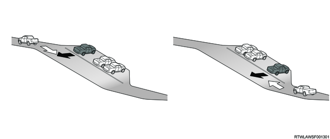
- A vehicle is continuously running up and down a steep slope
- A vehicle is running on a snowy road, or place where there is nothing around.
- The battery voltage decreases.
- Accessories such as a bicycle carrier are installed to the rear of the vehicle.
7) The radar sensor cannot detect an object.
- Small motorcycles, bicycles, or non-vehicle objects such as pedestrians
- Vehicles with shapes that do not easily reflect radar waves (sports cars, etc.)
- Stationary objects such as guard rails, walls, road signs, and parked vehicles
- Oncoming vehicle
- A vehicle behind running in the same lane as the own vehicle
- A vehicle running in a lane two lanes away from the lane where the own vehicle is running
- A vehicle in the adjacent lane that the own vehicle is trying to overtake
- The inter-vehicular distance between a vehicle and the own vehicle is small.
- A vehicle that is within the detection range of the radar sensor (within the range of Area B) but does not get close to the own vehicle. (The system determines the approaching vehicle based on the detection data of the radar sensor.)
- A vehicle behind running for a long time at almost the same speed as the own vehicle.
- A vehicle that is still in the detection area when the own vehicle starts moving from a stopped state
8) The blind spot monitor (BSM) operates even when there is no possibility of collision.
- A guard rail, road sign, parked vehicle, or other stationary objects are detected.
- A tunnel entrance, exit, or a turnout is detected.

- The tires are skidding.
- A vehicle is turning an intersection in an urban area or a crossing on multiple lanes.
3. Rear cross trafic alert (RCTA)
1. System activation
When the power mode (models with passive entry and start system) or the ignition switch (except models with passive entry and start system) is turned ON, the rear cross traffic alert (RCTA) function is turned ON.
2. System OFF setting
Using the MID mode switch of the steering wheel, the rear cross traffic alert (RCTA) function can be turned OFF by selecting Disable from the multi-information display settings in the instrument panel.
Note
- The rear cross traffic alert (RCTA) function is always reset to Enabled (ON) every time the ignition switch is turned ON.
- when towing another vehicle, turn OFF the rear cross traffic alert (RCTA) function. when towing another vehicle, the rear cross traffic alert (RCTA) function may not be activated because the radar wave irradiation cannot be performed.
MID mode switch
Legend
- MID mode L switch
- MID mode confirm switch
- MID mode R switch
Multi-Information Display
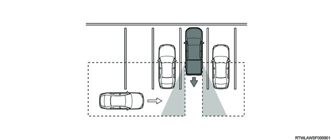
3. System operation
If the radar sensor detects a vehicle running on the rear right or rear left side when the vehicle moves backward from the parking space, the driver is alerted by flashing the blind spot indicator of the outside rearview mirror in the direction where a vehicle behind is detected and sounding the instrument panel cluster alarm.
Legend
- Blind spot indicator
Note
- When 2 vehicles are getting close to the own vehicle from rear right and rear left sides at the same time, both blind spot indicators of the right and left outside rearview mirrors flash.
1) Rear cross traffic alert (RCTA) operating conditions
Operates if all the following conditions are met.
- The Power mode (models with passive entry and start system) or the ignition switch (except models with passive entry and start system) is turned ON.
- The rear cross traffic alert (RCTA) function is ON.
- The vehicle speed is 10 km/h {6 mph} or less.
- The shift lever or selector lever is in the R position.
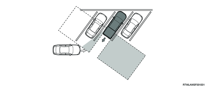
2) Detection range
The rear vehicle detection range of the rear cross traffic alert (RCTA) function is within the range of 25 m {82 ft} in width of rear right and rear left of the own vehicle.
Legend
- Detection range
Detection range
a: 1.0 m { 3.3 ft }
b: 4.5 m { 14.8 ft }
c: 25.0 m { 82.0 ft }
3) The rear cross traffic alert (RCTA) does not function normally.
- The position or direction of the radar sensor deviates due to the strong impact on the radar sensor or around the radar sensor.
- Mud, snow, ice, etc., adheres to the radar sensor or around the radar sensor.
- Difficulty in detecting a rear obstacle because of bad weather (heavy rain, blizzard, snow, etc.)
- The temperature around the radar sensor is high or low.
- Multiple vehicles are getting close to the own vehicle in a slight inter-vehicular distance.
- The own vehicle is extremely inclined.
- The radar sensor detection range is obstructed by the adjacent wall, parked vehicle, etc.
- The vehicle is parked at an angle.
- Another vehicle is running at a high speed and getting close to the own vehicle.
- The own vehicle moves back and gets out from the parking space on the slope
- Immediately after the shift lever or selector lever is shifted to the R position
- An object is placed around the radar sensor.
4) The radar sensor cannot detect an object.
- Small motorcycles, bicycles, or non-vehicle objects such as pedestrians
- Vehicles with shapes that do not easily reflect radar waves (sports cars, etc.)
- Stationary objects such as guard rails, walls, road signs, and parked vehicles
- A vehicle moving backward in the parking space next to the own vehicle
- A vehicle getting close from the parking space next to the own vehicle
- A vehicle approaching from directly behind the own vehicle
- A vehicle getting away from the own vehicle
5) The rear cross traffic alert (RCTA) function is activated even without the possibility of collision.
- A guard rail, wall, road sign, tree, parked vehicle, or other stationary objects at the rear of the vehicle are detected.
- A vehicle passes beside the own vehicle.
- The other vehicle is running on a road adjacent to the parking lot.
4. Radar sensor system components
1. Radar sensor
The radar sensor is a control unit that has a blind spot monitor (BSM) and rear cross traffic alert (RCTA) functions and that is installed inside the right and left steering step bumpers. It irradiates the left and right rear of the own vehicle with radar wave, and detects a vehicle in right and left rear blind spots or an approaching vehicle based on the radar wave reflection, and it measures the distance from the own vehicle and their relative speed. To activate each function, it receives signals from the related control units, and sends and receives information required for control via the CAN communication circuit.
The right and left of the radar sensor can be identified by "R" and "L" identifications on the protrusions of the radar sensors, or "RH" and "LH" identifications on the label on the back of the radar sensors.
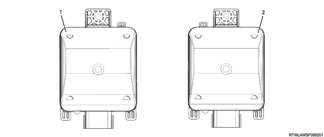
Legend
- Radar sensor (Left)
- Radar sensor (Right)
Back side label of the radar sensor
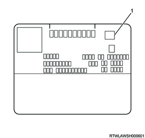
Legend
- Right and left identification display (RH or LH)
2. Blind spot indicator
The radar sensor illuminates or flashes the blind spot indicators in the right and left outside rearview mirrors via the BCM to alert the driver to the vehicle behind. The radar sensor controls the illumination, flashing, and OFF of the blind spot indicator via the CAN communication circuit and BCM. Adjustment of the brightness of the blind spot indicator is controlled by the BCM.
Legend
- Blind spot indicator
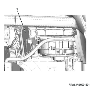
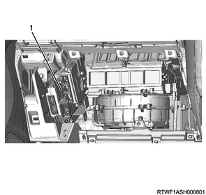
3. BCM
The BCM sends the turn signal and reverse signal to the radar sensor via the CAN communication circuit. In addition, the BCM receives the blind spot indicator illumination request signal, blind spot indicator flashing request signal, or blind spot indicator OFF request signal from the radar sensor via the CAN communication circuit when the blind spot monitor (BSM) and rear cross traffic alert (RCTA) are in operation. The BCM controls the blind spot indicator based on the received signal.
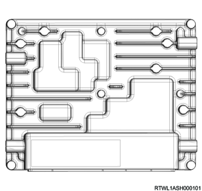
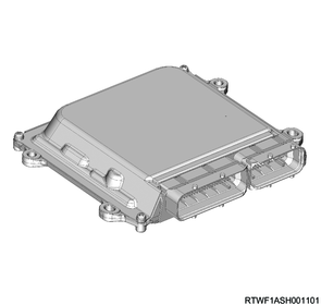
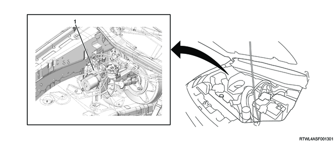
4. ECM
The ECM sends the vehicle speed signals to the radar sensor via the CAN communication circuit.
4JJ3 engine models
RZ4E engine models
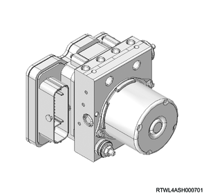
5. EHCU
The EHCU sends the wheel speed signal and yaw rate signal to the radar sensor via the CAN communication circuit.
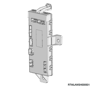
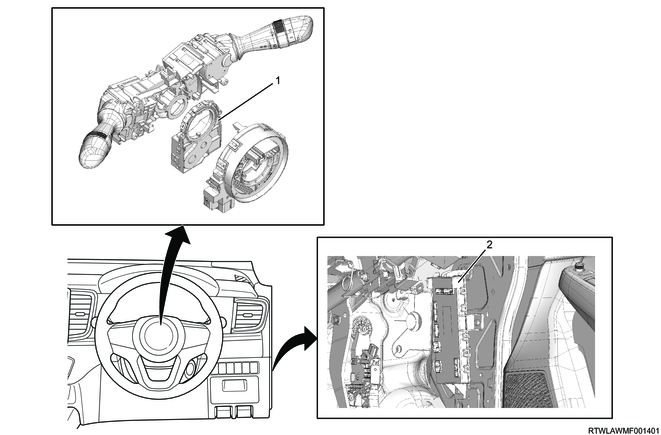
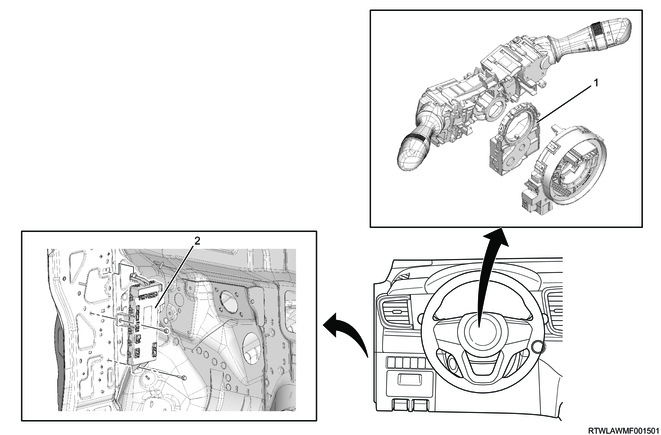
6. Steering angle sensor
The steering angle sensor is installed to the combination switch. It detects steering position, steering speed, and steering angle, and sends this information to the radar sensor via the CAN communication circuit.

Legend
- Steering angle sensor
- SRS coil
Caution
- Because the combination switch is integrated with the SRS coil, do not remove it or rotate the combination switch.
7. Instrument panel cluster
The radar sensor sends the information to the instrument panel cluster via the CAN communication circuit in order to control the warning light illumination in the instrument panel cluster and the warning displays on the multi-information display.
When the radar sensor detects a malfunction, the warning display is displayed on the multi-information display for approximately 5 seconds, and then it turns OFF.
1) BSM OFF indicator light
The BSM OFF indicator light illuminates when the blind spot monitor (BSM) function is turned to the Disable (OFF) from the multi-information display settings in the instrument panel. In addition, if a malfunction is found in the radar sensor, the BSM OFF indicator light illuminates.
2) Master warning indicator light
The master warning indicator light illuminates when a malfunction in the radar sensor is detected.
Note
- If a malfunction is found in the instrument panel cluster or parking aid system control unit, the master warning indicator light also illuminates, because it is a warning light common to the instrument panel cluster and parking aid system control unit.
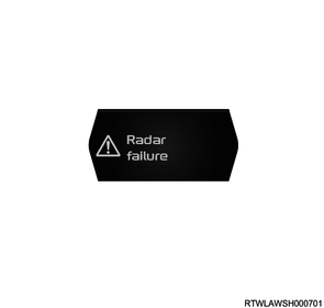
3) Radar sensor malfunction
When a system malfunction occurs, the following warnings are displayed on the multi-information display.
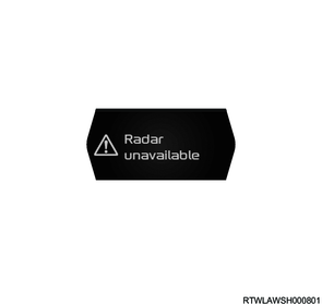
4) Abnormal radar sensor temperature
If the radar sensor detects the temperature in the radar sensor is 112°C {223°F} or more, or -40°C {-40°F} or less, it displays the following warnings on the multi-information display.
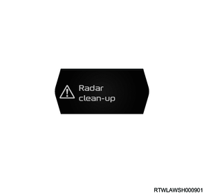
5) Foreign material detection by radar sensor
If the radar sensor detects any foreign material around the radar sensor, it displays the following warnings on the multi-information display.
5. Radar sensor system components views

Legend
- Radar sensor (Left)
- Radar sensor (Right)
RHD models
Legend
- Steering angle sensor
- BCM
LHD models
Legend
- Steering angle sensor
- BCM
4JJ3 engine models
Legend
- ECM
RZ4E engine models
Legend
- ECM
Legend
- EHCU
6. General circuit diagram
1. Radar sensor schematic
2. Radar sensor outline view and connector pin layout
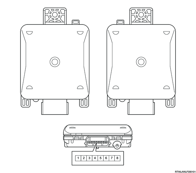
| PIN No. |
Pin function |
| 1 |
Ignition power supply |
| 2 |
Chassis CAN (High) |
| 3 |
- |
| 4 |
- |
| 5 |
Chassis CAN (Low) |
| 6 |
Ground |
| 7 |
Local CAN (High) |
| 8 |
Local CAN (Low) |
| PIN No. |
Pin function |
| 1 |
Ignition power supply |
| 2 |
Chassis CAN (High) |
| 3 |
Chassis CAN (High) |
| 4 |
Chassis CAN (Low) |
| 5 |
Chassis CAN (Low) |
| 6 |
Ground |
| 7 |
Local CAN (High) |
| 8 |
Local CAN (Low) |