1. Stereo camera system overview
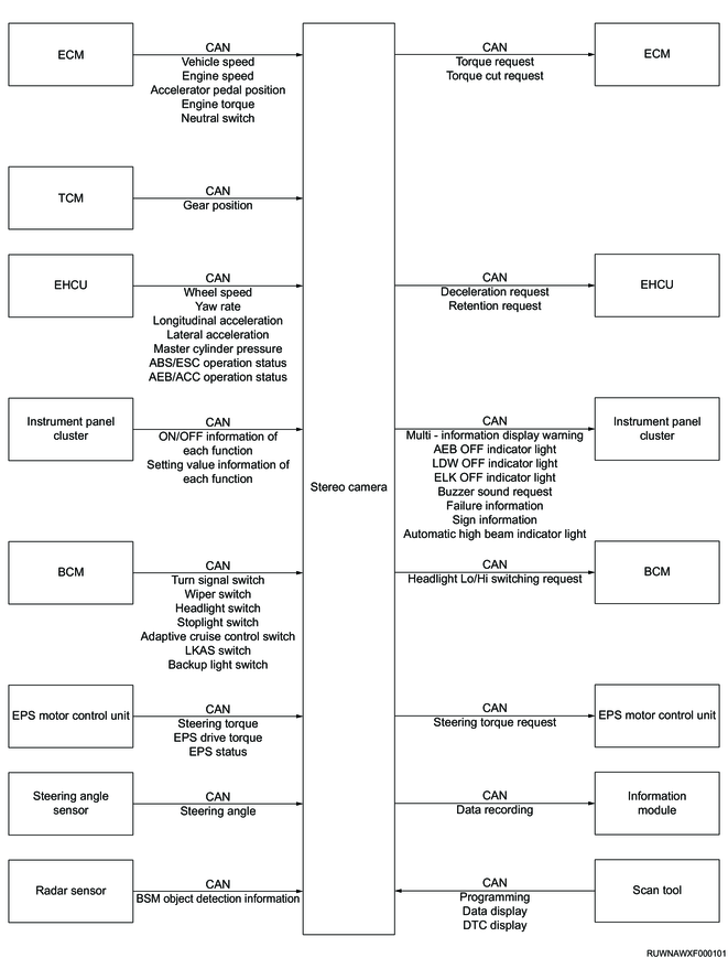
The stereo camera detects and recognizes a vehicle, pedestrian, bicycle, obstacle, lane, illuminant, sign, etc., in front of the own vehicle. The stereo camera controls the following functions based on the recognized information and current vehicle information.
- Lane Departure Warning
- Lane Departure Prevention (models equipped with EPS)
- Emergency Lane Keeping (models equipped with EPS)
- Lane Keep Assist System (models equipped with EPS)
- Attention Assist (models equipped with EPS)
- Autonomous Emergency Braking
- Pedal Misapplication Mitigation (automatic transmission model)
- Cruise Control
- Adaptive Cruise Control (automatic transmission model)
- Automatic High Beam
- Traffic Sign Recognition (for Australia and New Zealand)
- Intelligent Speed Limiter (for Australia and New Zealand)
- Manual Speed Limiter
Warning
- The stereo camera is intended to assist the driver's judgment and reduce accident damage and burden on the driver. Therefore, do not ever depend solely on the function of the stereo camera while driving. Even when each function is activated, perform the appropriate operation, such as depressing the brake pedal, as necessary by the driver's discretion. In addition, since the recognition performance and control of the stereo camera are limited, always keep in mind safe driving without depending on the function of the stereo camera.
Stereo camera input/output diagram
2. Stereo camera mechanism
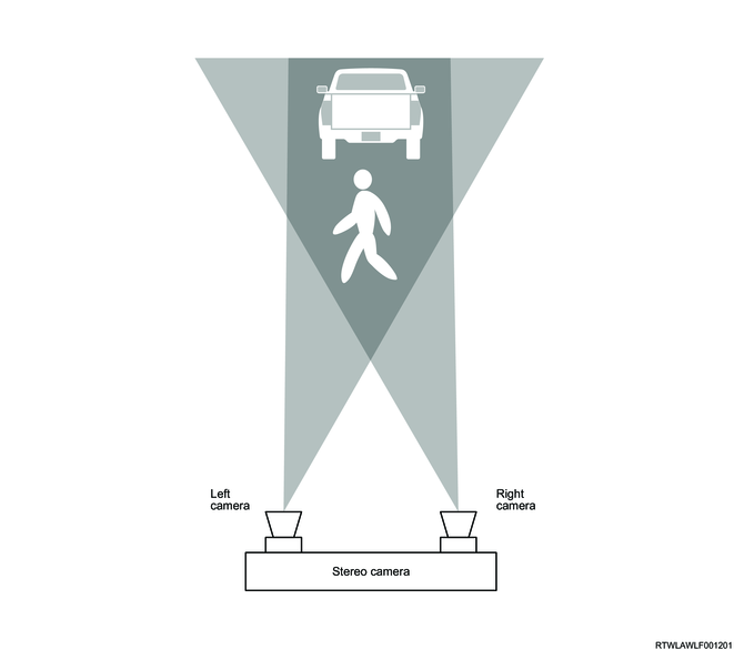
1. Principle of stereo camera
The stereo camera obtains the images from the left camera and right camera.
Illustration of obtaining images
There is a shifting between the right image and the left image, obtained by the stereo camera. When the obtained right and left images are overlaid, the shifting between right and left images is large if an object is in the near distance, and the shifting is small if it is in the distance. The stereo camera measures the distance to the object based on the detected degree of shifting.
Illustration of obtaining distance

Note
- The stereo camera has a similar characteristic to human eyes. Therefore, it is difficult for the stereo camera to recognize a vehicle, obstacle, and lane in front of the own vehicle under a condition where forward visibility is poor as well as for a driver.
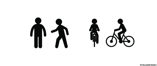
2. Pedestrian and cyclist recognition
The stereo camera recognizes an object as a pedestrian or cyclist based on the size, shape, and movement. It recognizes when the outlines of the object's head and shoulders are clear. However, the stereo camera cannot always recognize the pedestrian or cyclist. It may not recognize the pedestrian or cyclist under the following.
- Pedestrians are walking in group.
- A pedestrian or cyclist is near a wall or obstacle.
- A pedestrian or cyclist is putting up an umbrella.
- A pedestrian or cyclist wearing a similar color to the background blends in the landscape.
- A pedestrian or cyclist is holding a large luggage.
- A pedestrian or cyclist is leaning forward, crouching down, or lying down.
- A pedestrian or cyclist is outside the lighting range of the headlights or in a dark place.
- A pedestrian or cyclist on the side suddenly disappears.
- The own vehicle is too close to a pedestrian or cyclist.
- The pedestrian is riding a bicycle for children, a bicycle carrying large luggage, a bicycle with passenger(s), or a specially designed bicycle (a bicycle with a child seat, a tandem bicycle, etc.).
- The height of a pedestrian or cyclist is approximately 1 m {3 ft} or less, or approximately 2 m {7 ft} or more.
- The contours of pedestrians and cyclists are ambiguous (such as wearing a raincoat or long skirt)
- A pedestrian or cyclist is moving fast.
- A pedestrian is pushing a baby buggy, wheelchair, bicycle, etc.
3. Lane departure warning (LDW)
1. Lane departure warning (LDW) overview
The lane departure warning is a system that alerts the driver if the vehicle departs from its lane. The driver is alerted by an alarm sounded from the instrument panel cluster, vibration of the steering wheel, and indication on the multi-information display. This system operates when the vehicle speed is in the range of 60 km/h {37 mph} to 130 km/h {80 mph}.
Warning
- The purpose of the lane departure warning is to assist driving within lanes. This system does not aid driving without looking ahead carefully or assist hands-free driving.
2. System operation setting
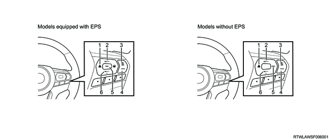
1) Models equipped with EPS
When Assist and warning or Warning only is selected by operating the MID mode switch, the lane departure warning is activated. If Off is selected with the MID mode switch, the LDW OFF indicator light illuminates and the lane departure warning is not activated. Even if the ignition switch is turned OFF with Warning only or Off selected, the lane departure warning is set to Assist and warning when the ignition switch is turned ON again.
2) Models without EPS
When Enable is selected by operating the MID mode switch, the lane departure warning is activated. If Disable is selected with the MID mode switch, the LDW OFF indicator light illuminates and the lane departure warning is not activated. For the lane departure warning, the previously selected set value is kept when the ignition switch is turned OFF and ON again.
MID mode switch
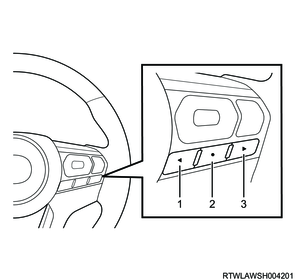
Legend
- MID mode L switch
- MID mode confirm switch
- MID mode R switch
Multi-Information Display (Models with EPS)
Multi-Information Display (Models without EPS)

| Specifications |
Screen display |
Description |
||
| Models equipped with EPS |
Lane support settings |
Lane departure prevention |
Assist and warning |
Select when activating both the lane departure warning and the lane departure prevention. |
| Warning only |
Select when activating only the lane departure warning. |
|||
| Off |
Select when setting both the lane departure warning and the lane departure prevention to OFF. |
|||
| Models without EPS |
Lane departure warning |
Enable |
Select when setting the lane departure warning to ON. |
|
| Disable |
Select when setting the lane departure warning to OFF. |
|||
Note
- Use the user customization function with the vehicle stopped. When running the vehicle during operation, the set value is reset.
3. System operation
When the stereo camera recognizes the lane markings on the road while driving in the vehicle speed range of 60 km/h {37 mph} to 130 km/h {80 mph}, the lane marking color displayed on the multi-information display turns white. The stereo camera monitors whether the vehicle departs the lane based on the recognized lane marking position information. When the vehicle departs from the lane, the warning screen is displayed on the multi-information display, and the lane marking color on the side where the lane departure is detected is displayed in yellow. At the same time, the warning by the steering wheel vibration is issued for models with EPS, and the warning by an alarm sounded from the instrument panel cluster is issued for models without EPS.

Multi-Information Display
Legend
- Left lane marker
- Right lane marker
| Multi-Information Display |
Lane marking color |
Description |
| Display area 1 |
None |
The stereo camera does not detect the lane. |
| White |
The stereo camera detects the lane. |
|
| Yellow |
The lane departure warning is in operation. |
|
| Display area 2 |
Gray |
The stereo camera does not detect the lane. |
| White |
The stereo camera detects the lane. |
4. Operating system conditions
The lane departure warning can be activated if all the following are met.
- The vehicle is running near the center of the road where there are lane markings drawn on one side or both sides.
- The vehicle speed is in the range of 60 km/h {37 mph} to 130 km/h {80 mph}.
- The vehicle is running straight ahead or turning a gentle curve.
- The LDW OFF indicator light does not illuminate.
5. Non-operating system conditions
The lane departure warning is not activated under the following.
- The turn signal switch is operated.
- The steering wheel is significantly or suddenly turned.
- The brake pedal is depressed.
- Suddenly accelerated.
- The vehicle is turning a sharp corner.
- The vehicle speed is less than approx. 60 km/h {37 mph}.
- Lane recognition became disabled while driving.
- The vehicle does not return to inside the lane after the system activation.
- The width of the lane marking is narrow.
- It is difficult to distinguish the color of the lane markings and road surface.
- The lane markings do not exist or are fading.
- The vehicle is turning a corner at an inappropriate speed.
6. System operating conditions even without possibility of lane departure
- There are tire tracks on wet roads, snowy roads, etc.
- It is difficult to distinguish between snow and a white line, or there is a white line for the repaired road.
- There is a shadow of something such as a guardrail.
- The lane marking is drawn in double lines.
- A line other than lane markings is drawn on the road surface.
4. Lane Departure Prevention (LDP)
1. Lane departure prevention (LDP) overview
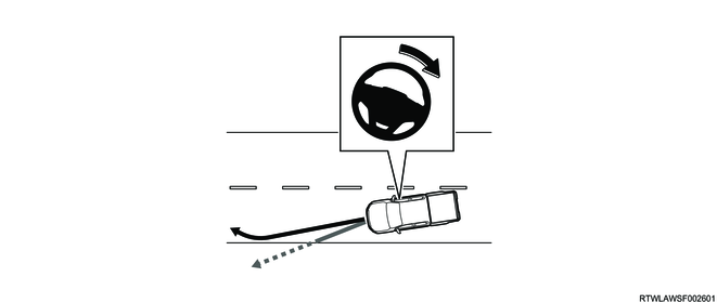
The lane departure prevention is a system that alerts a driver and assists in steering to prevent departure from the lane when it is determined that a vehicle may depart from the lane. The driver is alerted by vibration of the steering wheel and indication on the multi-information display. This system operates when the vehicle speed is in the range of 60 km/h {37 mph} to 130 km/h {80 mph}.
Warning
- The purpose of the lane departure prevention is to assist driving within lanes. This system does not aid driving without looking ahead carefully or assist hands-free driving.
Note
- If the lane departure warning cannot be used, the lane departure prevention is not activated.
2. System operation setting
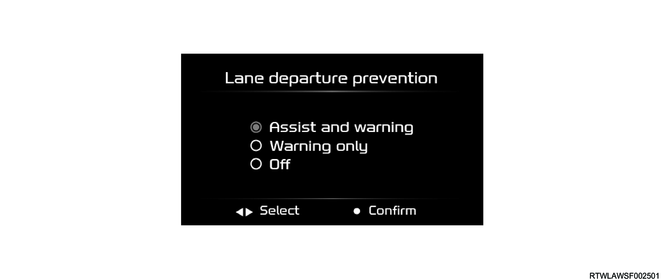
When Assist and warning is selected by operating the MID mode switch, the lane departure prevention is activated. When Warning only is selected with the MID mode switch, only the lane departure warning is activated. Also, if Off is selected, neither of the functions are activated and the LDW OFF indicator light illuminates. Even if the ignition switch is turned OFF with Warning only or Off selected, the lane departure prevention is set to Assist and warning when the ignition switch is turned ON again.
MID mode switch
Legend
- MID mode L switch
- MID mode confirm switch
- MID mode R switch
Multi-Information Display
| Screen display |
Description |
||
| Lane support settings |
Lane departure prevention |
Assist and warning |
Select when activating both the lane departure warning and the lane departure prevention. |
| Warning only |
Select when activating only the lane departure warning. |
||
| Off |
Select when setting both the lane departure warning and the lane departure prevention to OFF. |
||
Note
- Use the user customization function with the vehicle stopped. When running the vehicle during operation, the set value is reset.
3. System operation
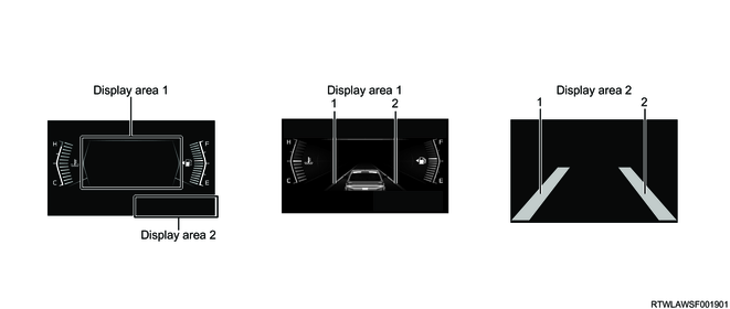
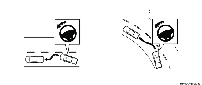
When the stereo camera recognizes the lane markings on the road while the vehicle is running in the vehicle speed range of 60 km/h {37 mph} to 130 km/h {80 mph}, the lane marking color displayed on the multi-information display turns white. The stereo camera monitors whether the vehicle departs from the lane based on the recognized lane marking position information. If the vehicle is about to depart from the lane, the steering assist is performed, the warning screen is displayed on the multi-information display, and the lane marking color on the side where the possibility of the lane departure is detected is displayed in yellow. At the same time, the warning by vibration of the steering wheel is issued.
Multi-Information Display
Legend
- Left lane marker
- Right lane marker
| Multi-Information Display |
Lane marking color |
Description |
| Display area 1 |
None |
The stereo camera does not detect the lane. |
| White |
The stereo camera detects the lane. |
|
| Yellow |
The lane departure prevention is in operation. |
|
| Display area 2 |
Gray |
The stereo camera does not detect the lane. |
| White |
The stereo camera detects the lane. |
4. Operating system conditions
Also, the lane departure prevention can be activated if all the following are met.
- The vehicle speed is in the range of 60 km/h {37 mph} to 130 km/h {80 mph}.
- A lane is recognized while running.
- The driver is holding the steering wheel.
- The lane width is not too narrow or too wide.
- The LDW OFF indicator light does not illuminate.
5. Non-operating system conditions
Also, the lane departure prevention is not activated or may not be able to sufficiently demonstrate its function under the following.
- The turn signal switch is operated.
- The hazard warning flasher switch is operated.
- The wipers are in operation at high speed.
- The steering wheel is suddenly turned.
- Sudden brake is applied.
- The vehicle is turning a corner.
- The vehicle speed is less than approx. 60 km/h {37 mph}.
- Lane recognition became disabled while driving.
- The LDP operating time is long.
- The LKAS is in operation.
- The ABS or TCS is in operation.
- Immediately after the vehicle weight changes significantly
- Immediately after replacing tires or adjusting the air pressure
- Immediately after adjusting, repairing, or replacing the stereo camera
- Immediately after repairing or replacing the suspension or steering-related parts
- Studless tires or non-genuine tires are installed.
- The vehicle is affected by crosswind.
- The gradient of the road changes suddenly (uphill or downhill).
- The lateral gradient of the road is extremely large or changes rapidly.
- Road conditions (shape, unevenness, etc.)
- Acceleration or deceleration is extreme.
- Outside temperature is high.
- The width of the lane is changed.
- The lane width is too narrow or too wide.
- The headlight does not illuminate at night or in a tunnel.
- It is dark in the evening or morning.
- Bad weather (rain, snow, etc.)
- Light reflects from the wet road.
- It is difficult to see the lane markings because the inter-vehicular distance to the preceding vehicle is short.
- Shadows of guard rails, etc., overlap the lane markings.
- The lane markings do not exist or are fading.
- It is difficult to distinguish the color of the lane markings and road surface.
- The lane marking is drawn in double lines.
- The width of the lane marking is narrow.
- A line other than lane markings is drawn on the road surface.
- A wall or pole is adjacent to the lane markings.
- The shape of the lane marking changes drastically (such as at the start or end of curves or continuously cranky/winding roads).
- The vehicle is approaching the lanes branching from the interchanges, junctions, rest area entrances, parking area entrances, etc., of an expressway.
- There are curbstones or sidewalls on the road shoulder.
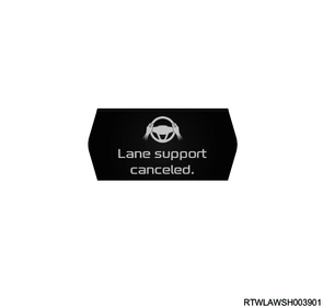
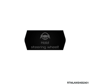
When the steering wheel has not been operated or has not been held for a predetermined period of time, an alarm sounds from the instrument panel cluster and the following warning screen is displayed on the multi-information display. At this time, the lane departure prevention is temporarily canceled.
5. Emergency Lane Keeping (ELK)
1. Emergency lane keeping (ELK) overview
The emergency lane keeping is a system that alerts the driver and assists in steering to prevent a collision with a vehicle approaching from the behind if it determines that there is a possibility of the collision during the lane change, regardless of the turn signal switch operation. The driver is alerted by an alarm sounded from the instrument panel cluster and the indication on the multi-information display. This system is activated when a lane change is performed while the BSM is operating in the vehicle speed range of approximately 60 km/h {37 mph} to 130 km/h {80 mph}.
Warning
- The purpose of the emergency lane keeping is to assist driving within a lane. This system is not for aiding drivers to change the lane without paying attention to the rear lateral direction, or to drive hands-free.
Note
- If the BSM cannot be used, the emergency lane keeping is not activated.
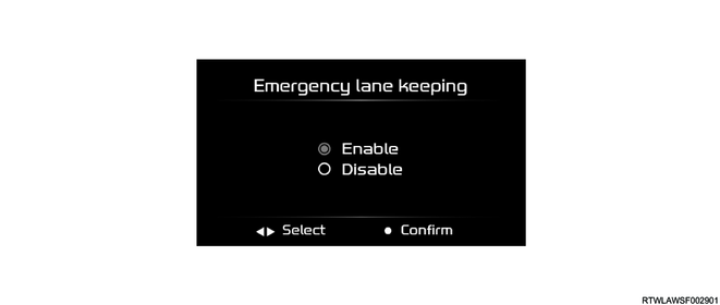
2. System operation setting
When Enable is selected by operating the MID mode switch, the emergency lane keeping is activated. When Disable is selected with the MID mode switch, the ELK OFF indicator light illuminates and the emergency lane keeping is not activated. Even if the ignition switch is turned OFF with Disable selected, the emergency lane keeping is set to Enable when the ignition switch is turned ON again.
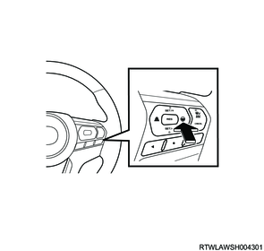
MID mode switch
Legend
- MID mode L switch
- MID mode confirm switch
- MID mode R switch
Multi-Information Display
| Screen display |
Description |
||
| Lane support settings |
Emergency lane keeping |
Enable |
Select when setting the emergency lane keeping to ON. |
| Disable |
Select when setting the emergency lane keeping to OFF. |
||
Note
- Use the user customization function with the vehicle stopped. When running the vehicle during operation, the set value is reset.
3. System operation
The stereo camera receives the BSM object detection information from the radar sensor via the CAN communication circuit. If the BSM operates and the stereo camera determines that there is a possibility of a collision with a vehicle approaching from behind during the lane change while driving in the vehicle speed range of approximately 60 km/h {37 mph} to 130 km/h {80 mph}, the steering is controlled to place the own vehicle back to the center of its lane, and the driver is alerted by an alarm sounded from the instrument panel cluster and the indication on the multi-information display.

Multi-Information Display
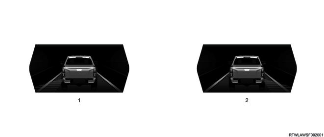
Legend
- A vehicle is approaching from rear left.
- A vehicle is approaching from rear right.
4. Operating system conditions
The emergency lane keeping can be activated if all the following are met.
- The ignition switch is in the ON position.
- The vehicle speed is in the range of 60 km/h {37 mph} to 130 km/h {80 mph}.
- The shift lever is in a position other than the R position.
- The ELK OFF indicator light or BSM OFF indicator light does not illuminate.
5. Non-operating system conditions
Also, the emergency lane keeping is not activated or may not be able to sufficiently demonstrate its function under the following.
- The wipers are in operation at high speed.
- The steering wheel is suddenly turned.
- Sudden brake is applied.
- The vehicle is turning a corner.
- The vehicle speed is no longer in the range of 60 km/h {37 mph} to 130 km/h {80 mph}
- Lane recognition became disabled while driving.
- The ELK operating time is long.
- The ABS or TCS is in operation.
- Immediately after the vehicle weight changes significantly
- Immediately after replacing tires or adjusting the air pressure
- Immediately after adjusting, repairing, or replacing the stereo camera
- Immediately after repairing or replacing the suspension or steering-related parts
- Studless tires or non-genuine tires are installed.
- The vehicle is affected by crosswind.
- The gradient of the road changes suddenly (uphill or downhill).
- The lateral gradient of the road is extremely large or changes rapidly.
- Road conditions (shape, unevenness, etc.)
- Acceleration or deceleration is extreme.
- Outside temperature is high.
- The width of the lane is changed.
- The lane width is too narrow or too wide.
- The headlight does not illuminate at night or in a tunnel.
- It is dark in the evening or morning.
- Bad weather (rain, snow, etc.)
- Light reflects from the wet road.
- It is difficult to see the lane markings because the inter-vehicular distance to the preceding vehicle is short.
- Shadows of guard rails, etc., overlap the lane markings.
- The lane markings do not exist or are fading.
- It is difficult to distinguish the color of the lane markings and road surface.
- The lane marking is drawn in double lines.
- The width of the lane marking is narrow.
- A line other than lane markings is drawn on the road surface.
- A wall or pole is adjacent to the lane markings.
- The shape of the lane marking changes drastically (such as at the start or end of curves or continuously cranky/winding roads).
- The vehicle is approaching the lanes branching from the interchanges, junctions, rest area entrances, parking area entrances, etc., of an expressway.
- There are curbstones or sidewalls on the road shoulder.
When the steering wheel has not been operated or has not been held for a predetermined period of time, an alarm sounds from the instrument panel cluster and the following warning screen is displayed on the multi-information display. At this time, the emergency lane keeping is temporarily canceled.
6. Lane Keep Assist System (LKAS)
1. Lane keep assist system (LKAS) overview
The lane keep assist system is a system that assists in steering while the vehicle is running with the adaptive cruise control so that the vehicle can keep running in the middle of the lane based on the lane marking position information detected by the stereo camera. This system operates when the vehicle speed is in the range of 60 km/h {37 mph} to 130 km/h {80 mph}.
Warning
- The purpose of the lane keep assist system is to assist driving within lanes. This system does not aid driving without looking ahead carefully or assist hands-free driving.
2. System activation
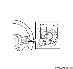
The lane keep assist system is activated by pressing the LKAS switch while driving with adaptive cruise control. At this time, the LKAS indicator light illuminates in gray.
LKAS switch
Multi-Information Display
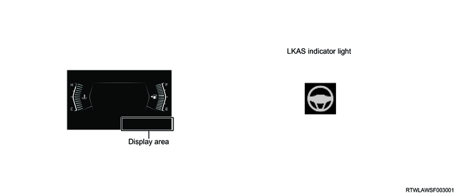
3. System operation
When the stereo camera recognizes the lane markings on the road while the vehicle is running with the adaptive cruise control in the vehicle speed range of 60 km/h {37 mph} to 130 km/h {80 mph}, the lane marking color displayed on the multi-information display turns white. The stereo camera assists in steering so that the vehicle can keep running in the middle of the lane based on the recognized lane marking position information. At the same time, the operation screen is displayed on the multi-information display and the LKAS indicator light illuminates in green.
Legend
- Driving straight
- When turning
Multi-Information Display
Legend
- Left lane marker
- Right lane marker
| Multi-Information Display |
Lane marking color |
Description |
| Display area 1 |
None |
The stereo camera does not detect the lane. |
| White |
The stereo camera detects the lane. |
|
| Green |
The lane keep assist system is in operation. |
|
| Display area 2 |
Gray |
The stereo camera does not detect the lane. |
| White |
The stereo camera detects the lane. |
|
| Green |
The lane keep assist system is in operation. |
4. Operating system conditions
The lane keep assist system can be activated if all the following are met.
- The adaptive cruise control is in operation.
- The vehicle speed is in the range of 60 km/h {37 mph} to 130 km/h {80 mph}.
- A lane is recognized while running.
- The driver is holding the steering wheel.
- The vehicle is running on a road with a lane width of 3 m {10 ft} to 4 m {13 ft}.
5. Non-operating system conditions
The lane keep assist system is not activated or may not be able to sufficiently demonstrate its function under the following.
- The turn signal switch is operated.
- The hazard warning flasher switch is operated.
- The wipers are in operation at high speed.
- Sudden brake is applied.
- The vehicle is turning a sharp corner.
- The vehicle is entering a sharp curve.
- The vehicle speed is no longer in the range of 60 km/h {37 mph} to 130 km/h {80 mph}
- Lane recognition on both sides becomes disabled while running.
- The ABS or TCS is in operation.
- The vehicle is not running with the adaptive cruise control.
- Immediately after the vehicle weight changes significantly
- Immediately after replacing tires or adjusting the air pressure
- Immediately after adjusting, repairing, or replacing the stereo camera
- Immediately after repairing or replacing the suspension or steering-related parts
- Studless tires or non-genuine tires are installed.
- The vehicle is affected by crosswind.
- The gradient of the road changes suddenly (uphill or downhill).
- The lateral gradient of the road is extremely large or changes rapidly.
- Road conditions (shape, unevenness, etc.)
- Acceleration or deceleration is extreme.
- Outside temperature is high.
- The system determines that the vehicle is departed from the lane by the driver's operating the steering wheel.
- The steering wheel is significantly or suddenly turned.
- The lane width is too narrow or too wide.
- There is a malfunction in other systems related to the lane keep assist system.
When the steering wheel has not been operated or has not been held for a predetermined period of time, an alarm sounds from the instrument panel cluster and the following warning screen is displayed on the multi-information display.
If driving without holding the steering wheel is continued, the following warning screen is displayed on the multi-information display, and the lane keep assist system is temporarily canceled.
7. Attention Assist
1. Attention assist overview
The attention assist is a system that alerts the driver when vehicle wandering is detected. The driver is alerted by an alarm sounded from the instrument panel cluster and the indication on the multi-information display. This system operates when the vehicle speed is approximately 60 km/h {37 mph} or more.
Warning
- The purpose of the attention assist is to assist driving within lanes. This system does not aid driving without looking ahead carefully or assist hands-free driving.
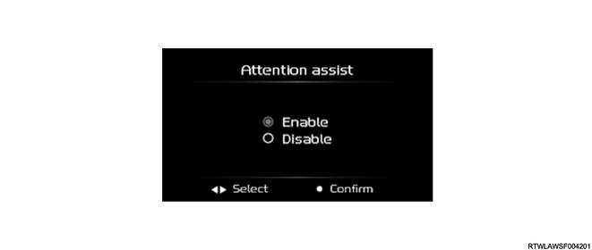
2. System operation setting
When Enable is selected by operating the MID mode switch, the attention assist is activated. When Disable is selected with the MID mode switch, the attention assist is not activated. Even if the ignition switch is turned OFF with Disable selected, the attention assist is set to Enable when the ignition switch is turned ON again.
MID mode switch
Legend
- MID mode L switch
- MID mode confirm switch
- MID mode R switch
Multi-Information Display
| Screen display |
Description |
||
| Lane support settings |
Attention assist |
Enable |
Select when setting the attention assist to ON. |
| Disable |
Select when setting the attention assist to OFF. |
||
Note
- Use the user customization function with the vehicle stopped. When running the vehicle during operation, the set value is reset.
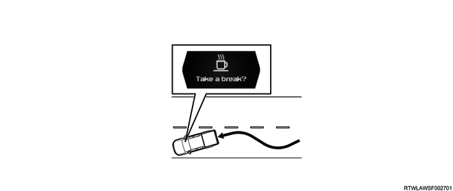
3. System operation
When the vehicle speed is approximately 60 km/h {37 mph} or more, the stereo camera monitors whether the vehicle is wandering based on the recognized lane marking position information. When the vehicle starts wandering, the driver is alerted by an alarm sounded from the instrument panel cluster and indication on the multi-information display.
4. Non-operating system conditions
If the vehicle is wandering immediately after running, the attention assist is not activated. Also, the attention assist may not be activated under the following.
- The vehicle runs on consecutive curves.
- The vehicle speed changes significantly.
- Immediately after changing the lane
Note
- When the vehicle speed becomes less than approximately 40 km/h {25 mph}, the attention assist stops operating. When the vehicle speed reaches approximately 60 km/h {37 mph} or more from this state, the attention assist resumes.
8. Autonomous Emergency Braking (AEB)
1. Autonomous emergency braking (AEB) overview
The AEB is a system that uses a stereo camera to determine the distance and relative speed to the obstacle that may be collided with. If the stereo camera detects an object where the vehicle cannot avoid a collision, the system activates the automatic brake in order to reduce damage caused by the collision. The driver is alerted by an alarm sounded from the instrument panel cluster, forward collision warning light flashing, and indication on the multi-information display. If no preventive operation is performed, the automatic brake is activated. This system operates when the vehicle speed is in the range of 8 km/h {5 mph} to 160 km/h {100 mph}.
Warning
- The AEB is not a system that assists in the driving operation and automatically avoids collision, or stops the vehicle safely. It is necessary not to overly trust the system and to keep in mind safe driving.
2. System operation setting
When Enable is selected by operating the MID mode switch, the AEB is activated. When Disable is selected with the MID mode switch, the AEB OFF indicator light illuminates and the AEB is not activated. Even if the ignition switch is turned OFF with Disable selected, the AEB is set to Enable even when the ignition switch is turned ON again.
3. Alarm distance setting
By operating the MID mode switch, the AEB alarm distance (far/normal/near) can be selected. For the AEB alarm distance, the previously selected set value is kept when the ignition switch is turned OFF and ON again.
MID mode switch
Legend
- MID mode L switch
- MID mode confirm switch
- MID mode R switch
Multi-Information Display

| Screen display |
Description |
||
| Automatic emergency brake settings |
Brake and warning intervention |
Enable |
Select when setting AEB to ON. |
| Disable |
Select when setting AEB to OFF. |
||
| Warning sensitivity* |
Far |
Select when setting the alarm distance to Far. |
|
| Normal |
Select when setting the alarm distance to Standard. |
||
| Near |
Select when setting the alarm distance to Near. |
||
| *: Warning sensitivity can be set only when Brake and warning intervention is set to Enable. |
|||
Note
- Use the user customization function with the vehicle stopped. When running the vehicle during operation, the set value is reset.
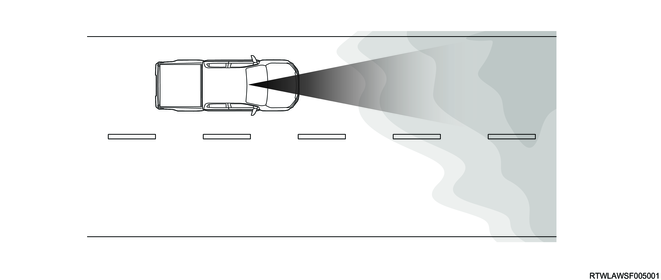
4. System operation
The stereo camera measures the distance from an obstacle detected ahead and their relative speed based on the images obtained from the right and left cameras. It also recognizes an object. When the own vehicle approaches the preceding vehicle or an obstacle that may be collided with, the driver is alerted by an alarm sounded from the instrument panel cluster and indication on the multi-information display. If no preventive operation is performed, the automatic brake is activated.
Note
- A noise may be heard when the AEB is activated. This is not a malfunction as this sound occurs when the system is activated.
- If the warning is activated when the own vehicle overtakes the preceding vehicle, do not approach further. The automatic brake may be activated if the vehicle is getting too close to the preceding vehicle
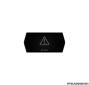
1) Forward collision warning (FCW)
When the own vehicle approaches the preceding vehicle or an obstacle that may be collided with, the driver is alerted by an alarm sounded from the instrument panel cluster, forward collision warning light flashing, and the following screen indicated on the multi-information display. When the vehicle is decelerated and an appropriate inter-vehicular distance is reached by driver's depressing the brake pedal, the warning is canceled.
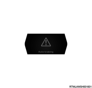
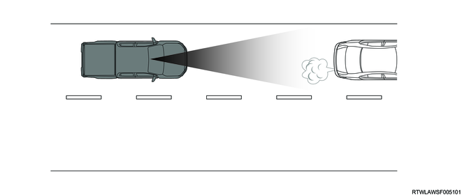
2) Auto braking phase
If no preventive operation is performed when approaching the preceding vehicle or an obstacle that may be collided with, the automatic brake is activated. At this time, an alarm sounds from the instrument panel cluster, the forward collision warning light flashes, and the following warning screen is displayed on the multi-information display. If the possibility of a collision is reduced by driver's depressing the brake pedal, the automatic brake is released.
AEB operation example

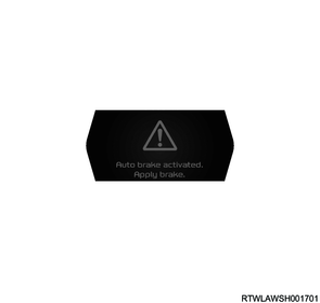
3) Cancellation of the automatic brake
After the automatic brake is activated, the following warning screen is displayed on the multi-information display, indicating that the automatic brake has been activated and prompting the brake pedal operation.
When the vehicle is not stopped
When the vehicle is stopped
4) Operating system conditions
The AEB can be activated if all the following are met.
- The ignition switch is in the ON position.
- The vehicle runs forward at 8 km/h {5 mph} or more.
- The AEB OFF indicator light does not illuminate.
Note
- The AEB is not temporarily operated when the AEB is activated 3 times after starting the engine. At this time, "Front camera unavailable" is displayed on the multi-information display and the AEB OFF indicator light illuminates. The AEB resumes when the engine starts again.
5) Non-operating system conditions
The AEB is not activated under the following.
- The vehicle speed is no longer in the range of 8 km/h {5 mph} to 160 km/h {100 mph}.
- The ABS is in operation.
- The ESC is in operation or is malfunctioning.
- The lateral position of the own vehicle significantly deviates from the preceding vehicle.
- The stereo camera function is temporarily deactivated due to poor visibility, etc.
Also, the AEB may not be able to sufficiently demonstrate its function under the following.
- Vehicle conditions (weight of cargo, number of occupants, etc.)
- Road conditions (gradient, slipperiness, shape, unevenness, etc.)
- Vehicle maintenance (brake-related parts, tire wear, tire air pressure, etc.)
- The outside air temperature is low, or the brake is cold immediately after the vehicle is started.
- The engine is cold immediately after the vehicle starts running.
- If the brake pedal is operated frequently, the brake is overheated and the effectiveness becomes poor.
- The vehicle is running on a puddle or the brake is wet after washing the vehicle.
6) The system operating conditions without possibility of collision
- The vehicle passes through a toll gate at a speed exceeding the specified one.
- Before a parking bar or railroad crossing bar fully goes up.
- The own vehicle is running near the preceding vehicle.
- The vehicle is running on a road whose gradient changes suddenly.

- Visibility is poor due to splashes from the preceding or oncoming vehicle, snow, dust, water vapor, sand, smoke, etc.
- The vehicle passes through vapor or smoke.
- Bad weather (storm, blizzard, snow, etc.)
- The exhaust gas emitted from the preceding vehicle is clearly visible in a cold region, etc.
- There is an object at the entrance of a curved road or intersection

- The vehicle passes by an oncoming vehicle on a curve.
- The vehicle passes through other vehicles or obstacles.
- Stop the vehicle near another vehicle or a wall.
- The vehicle passes through water sprayed from pipes to melt snow or water sprayed from sprinkler trucks.
- Boarding or driving within a ferry
5. Turn assist (for Australia, New Zealand, and South Africa)
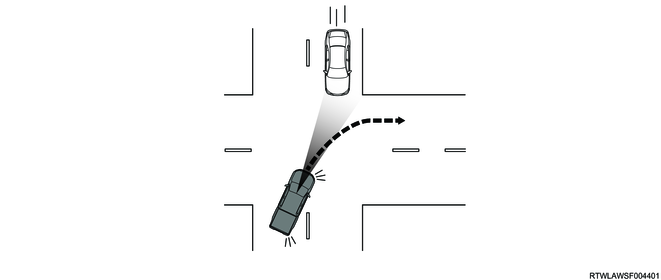
1) Turn assist overview
The turn assist is a system that avoids collision or reduces damage at the time of the collision by the warning (FCW) and by activating the automatic brake (AEB) if it determines that there is a possibility of collision with an oncoming vehicle when the own vehicle turns at an intersection. The driver is alerted by an alarm sounded from the instrument panel cluster and the indication on the multi-information display. This system operates when the vehicle speed is in the range of 5 km/h {3 mph} to 18 km/h {11 mph}.
Warning
- The turn assist is not a system that automatically avoids collision or stops the vehicle safely to assist in the driving operation. It is necessary not to overly trust the system and to keep in mind safe driving.
Note
- If the AEB cannot be used, the turn assist is not activated.
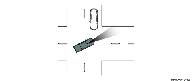
2) System operation
The stereo camera measures the distance from an obstacle detected ahead and their relative speed based on the images obtained from the right and left cameras. It also recognizes an object. If no preventive operation is performed when the vehicle approaches an oncoming vehicle that may be collided with when turning right, the automatic brake is activated.
3) Operating system conditions
The turn assist operates if all the following are met.
- The turn signal switch is operated.
- The vehicle speed is 18 km/h {11 mph} or less.
- An oncoming vehicle is running at a speed of approximately 40 km/h {25 mph} or more.
4) Non-operating system conditions
The turn assist may not be able to sufficiently demonstrate its function under the following.
- An oncoming vehicle is in a lane more than 2 lanes away from the own vehicle lane when the own vehicle turns right.
- The direction of the own vehicle shifts significantly from the direction directly opposite to the oncoming lane when the own vehicle turns right.
5) The system operating conditions without possibility of collision
- An oncoming vehicle passes through in front of the vehicle that is turning right.
- The own vehicle is about to pass nearby an oncoming vehicle during a right turn.
- An oncoming vehicle has stopped just in front of the own vehicle that is turning right.
- An oncoming vehicle is turning right or left when the own vehicle is turning right.
- The steering wheel is operated to allow the own vehicle to approach an oncoming vehicle.

9. Pedal Misapplication Mitigation
1. Pedal misapplication mitigation overview
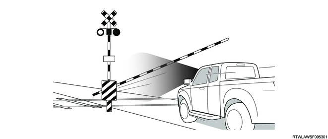
The pedal misapplication mitigation is a system that limits the engine output to slow down the start when the system determines that the accelerator pedal has been depressed more than necessary due to pedal misapplication, etc., with the stereo camera recognizing an obstacle in front of the vehicle while the vehicle is stopped or driving slowly. The driver is alerted by an alarm sounded from the instrument panel cluster, forward collision warning light flashing, and indication on the multi-information display. This system operates when the vehicle speed is within approximately 10 km/h {6 mph}.
Warning
- The pedal misapplication mitigation is not a system that assists in the driving operation and automatically avoids collision, or stops the vehicle safely. It is necessary not to overly trust the system and to keep in mind safe driving.
Note
- If the AEB cannot be used, the pedal misapplication mitigation is not activated.
2. System operation setting
The pedal misapplication mitigation is linked to the AEB and is activated when the AEB is set to Enable by operating the MID mode switch. When the AEB is set to Disable with the MID mode switch, the AEB OFF indicator light illuminates and the AEB and pedal misapplication mitigation are not activated. Even when the ignition switch is turned OFF with Disable selected, the pedal misapplication mitigation is set to Enable when the ignition switch is turned ON again, because the pedal misapplication mitigation is linked to the AEB.
MID mode switch
Legend
- MID mode L switch
- MID mode confirm switch
- MID mode R switch
Multi-Information Display
| Screen display |
Description |
||
| Automatic emergency brake settings |
Brake and warning intervention |
Enable |
Select when setting the pedal misapplication mitigation to ON. |
| Disable |
Select when setting the pedal misapplication mitigation to OFF. |
||
Note
- Use the user customization function with the vehicle stopped. When running the vehicle during operation, the set value is reset.
3. System operation
The stereo camera measures the distance from an obstacle detected ahead and their relative speed based on the images obtained from the right and left cameras. When the accelerator pedal is depressed more than necessary due to pedal misapplication, etc., while the vehicle is stopped or driving slowly, the engine output is limited to slow down the start. At this time, the driver is alerted by an alarm sounded from the instrument panel cluster, forward collision warning light flashing, and indication on the multi-information display.

1) The system is in operation.
The following warning screen is displayed on the multi-information display while the pedal misapplication mitigation is in operation.
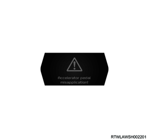
2) After system activation
The following warning screen is displayed on the multi-information display after the pedal misapplication mitigation is activated.

4. Non-operating system conditions
Also, the pedal misapplication mitigation is not activated or is deactivated under the following.
- The accelerator pedal is depressed for 3 seconds or more.
- The accelerator pedal is released.
- The shift lever is operated to a position other than D.
- The steering wheel is significantly or suddenly turned.
- The engine is stopped.
- The AEB OFF indicator light illuminates.
5. The system operating conditions without possibility of collision
- Before a parking bar or railroad crossing bar fully goes up.
- The exhaust gas emitted from the preceding vehicle is clearly visible in a cold region, etc.
- The own vehicle is running near the preceding vehicle.
- The vehicle is running on a road whose gradient changes suddenly.
- The vehicle runs through a puddle, or water, snow, water vapor, sand, smoke, etc., splashes from the preceding vehicle.
- The vehicle passes through water sprayed from pipes to melt snow or water sprayed from sprinkler trucks.
- Bad weather (heavy snow, blizzard, etc.)
- There is an object at the entrance of a curved road or intersection
- The vehicle passes through other vehicles or obstacles.
- Stop the vehicle near another vehicle or a wall.
- The vehicle is running through a riverbed, overgrown bushes, or forest.
10. Cruise Control
1. Cruise control overview
The cruise control is a system that reduces the burden on the driver by maintaining the set speed without depressing the accelerator pedal. This system operates when the vehicle speed is in the range of 30 km/h {20 mph} to 160 km/h {100 mph}.
Warning
- The cruise control does not accelerate/decelerate according to the inter-vehicular distance with the preceding vehicle. Operate the accelerator pedal or brake pedal according to the inter-vehicular distance between the own vehicle and the preceding vehicle.
2. System activation
1) Models with adaptive cruise control
When pressing the main switch, first the adaptive cruise control indicator light illuminates in white. When the inter-vehicular distance switch is pressed for 2 seconds or more in this state, the cruise control indicator light turns in white and switches to the cruise control.
Automatic transmission model
Legend
- Inter-vehicular distance switch
- SET/+ switch
- Main switch
- CANCEL switch
- RES switch
- SET/- switch
2) Models without adaptive cruise control
The cruise control switch is activated by pressing the main switch. At this time, the cruise control indicator light illuminates in white.
Manual transmission model
Legend
- SET/- switch
- RES switch
- SET/+ switch
- Main switch
- CANCEL switch
Cruise control indicator light
3. Setting and changing of vehicle speed
The vehicle speed can be arbitrarily set by operating the pedal or set switch, and the activation of the cruise control is started.
1) Acceleration of vehicle speed
< Acceleration of set vehicle speed by accelerator pedal operation>
The vehicle speed is set by pressing the SET switch when the desired vehicle speed is reached by adjusting the depression of the accelerator pedal. At the time, the set vehicle speed is displayed on the multi-information display, and the cruise control indicator light illuminates in green.
<Acceleration of set vehicle speed by SET/+ switch operation>
The vehicle speed indicated on the multi-information display changes while the SET/+ switch is pressed. When the switch is short pressed, the vehicle speed increases by 1 km/h {1 mph} and when it is long pressed, the speed increases by 5 km/h {5 mph}. When releasing the SET/+ switch at the desired vehicle speed, the vehicle speed is set as the desired one, and the cruise control indicator light illuminates in green.
2) Deceleration of vehicle speed
<Deceleration of set vehicle speed by brake pedal operation>
The vehicle speed is set by pressing the SET switch when the desired vehicle speed is reached by adjusting the depression of the brake pedal. At the time, the set vehicle speed is displayed on the multi-information display, and the cruise control indicator light illuminates in green.
<Deceleration of set vehicle speed by SET/- switch operation>
The vehicle speed indicated on the multi-information display changes while the SET/- switch is pressed. When the switch is short pressed, the vehicle speed decreases by 1 km/h {1 mph} and when it is long pressed, the speed decreases by 5 km/h {5 mph}. When releasing the SET/- switch at the desired vehicle speed, the vehicle speed is set as the desired one, and the cruise control indicator light illuminates in green.
4. System operation
The stereo camera controls the cruise control based on the vehicle speed and cruise control switch information. While driving with cruise control, the vehicle runs at a constant speed within the set vehicle speed range (30 km/h {20 mph} to 160 km/h {100 mph}).
5. System deactivation or cancellation
1) System deactivation
If the main switch is pressed while driving with the cruise control, the cruise control is turned OFF. When the cruise control is turned OFF, the cruise control indicator light turns OFF.
2) System cancellation
The cruise control is canceled if any of the following is met while driving with the cruise control. At this time, the following cancellation screen is displayed on the multi-information display for 5 seconds, and then the color of the cruise control indicator light switches from green to white.
- The brake pedal is depressed.
- The clutch pedal is depressed (manual transmission models).
- The vehicle speed is approximately 30 km/h {20 mph} or less.
- There is a malfunction in the engine control system.
- The shift control is operated.
- The CANCEL switch is pressed.
- The vehicle is temporarily stopped and the shift lever is operated to the N position (automatic transmission model).
- The ESC or TCS is in operation.

6. System restore
It is possible to return the cruise control running state before the cancellation by operating the RES switch. When the cruise control is restored, the color of the cruise control indicator light switches from white to green.
11. Adaptive Cruise Control (ACC)
1. Adaptive cruise control (ACC) overview
The adaptive cruise control is a system that uses a stereo camera to determine the distance and relative speed to the preceding vehicle, automatically accelerates/decelerates/stops the vehicle to maintain the inter-vehicular distance, and reduces the burden on the driver. This system operates when the vehicle speed is in the range of 30 km/h {20 mph} to 130 km/h {80 mph}.
Warning
- The adaptive cruise control is a system that reduces the burden on the driver, and is not a danger avoidance system such as collision prevention. It is necessary not to overly trust the system and to keep in mind safe driving.
2. System activation
The adaptive cruise control is activated by pressing the main switch. At this time, the adaptive cruise control indicator light illuminates in white.
Legend
- Inter-vehicular distance switch
- SET/+ switch
- Main switch
- CANCEL switch
- RES switch
- SET/- switch
Adaptive cruise control indicator light
3. Setting and changing of vehicle speed
The vehicle speed can be arbitrarily set by operating the pedal or set switch, and the adaptive cruise control starts to operate.
1) Acceleration of vehicle speed
< Acceleration of set vehicle speed by accelerator pedal operation>
The vehicle speed is set by pressing the SET switch when the desired vehicle speed is reached by adjusting the depression of the accelerator pedal. At the time, the set vehicle speed is displayed on the multi-information display, and the adaptive cruise control indicator light illuminates in green.
<Acceleration of set vehicle speed by SET/+ switch operation>
The vehicle speed indicated on the multi-information display changes while the SET/+ switch is pressed. When the switch is short pressed, the vehicle speed increases by 1 km/h {1 mph} and when it is long pressed, the speed increases by 5 km/h {5 mph}. When releasing the SET/+ switch at the desired vehicle speed, the vehicle speed is set as the desired one, and the adaptive cruise control indicator light illuminates in green.
2) Deceleration of vehicle speed
<Deceleration of set vehicle speed by brake pedal operation>
The vehicle speed is set by pressing the SET switch when the desired vehicle speed is reached by adjusting the depression of the brake pedal. At the time, the set vehicle speed is displayed on the multi-information display, and the adaptive cruise control indicator light illuminates in green.
<Deceleration of set vehicle speed by SET/- switch operation>
The vehicle speed indicated on the multi-information display changes while the SET/- switch is pressed. When the switch is short pressed, the vehicle speed decreases by 1 km/h {1 mph} and when it is long pressed, the speed decreases by 5 km/h {5 mph}. When releasing the SET/- switch at the desired vehicle speed, the vehicle speed is set as the desired one, and the adaptive cruise control indicator light illuminates in green.
4. Inter-vehicular distance setting
There are 3 level settings for the inter-vehicular distance, which can be changed by operating the inter-vehicular distance switch. Every time the inter-vehicular distance switch is pressed, the inter-vehicle distance indicated on the multi-information display is changed.
Legend
- Inter-vehicular distance switch
- SET/+ switch
- Main switch
- CANCEL switch
- RES switch
- SET/- switch
Multi-Information Display
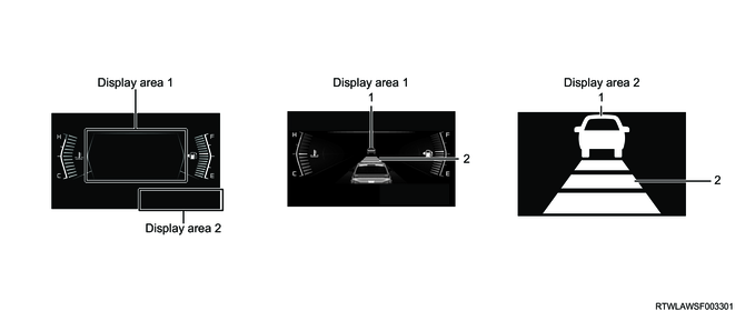
Legend
- Preceding vehicle indicator
- Inter-vehicular distance display
| Screen display |
Description |
| Preceding vehicle indicator |
It is displayed when the stereo camera recognizes the preceding vehicle. |
| Inter-vehicular distance display |
The set inter-vehicle distance (short/medium/long) from the preceding vehicle is displayed. |
5. System operation
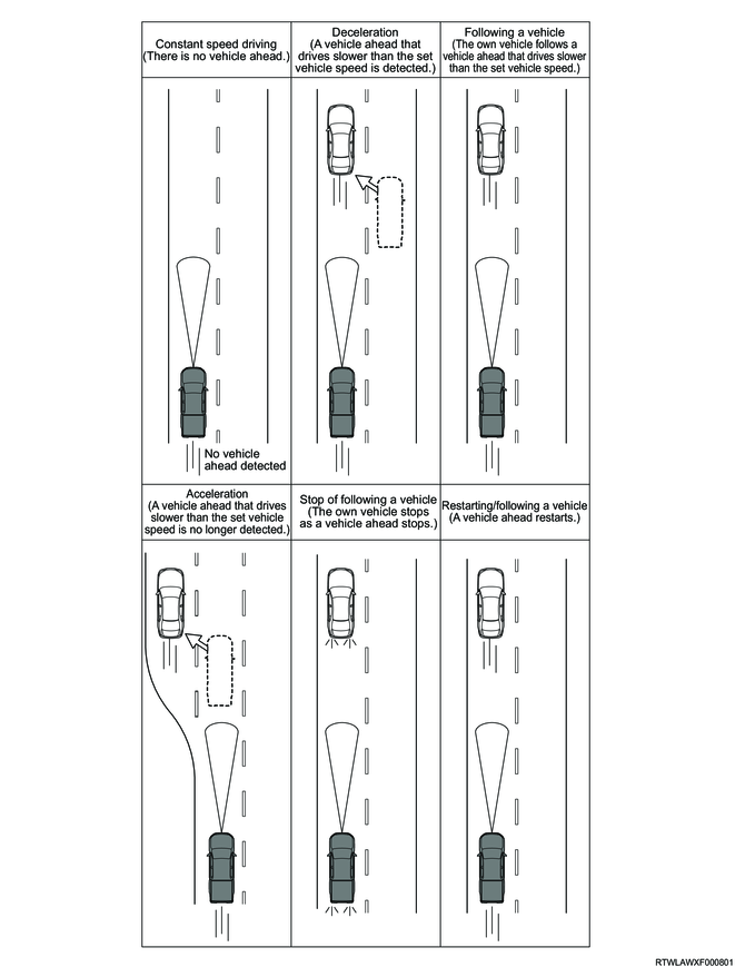
An appropriate inter-vehicular distance from the preceding vehicle on the white lane is maintained by the stereo camera. While driving with adaptive cruise control, acceleration, deceleration, and stop are automatically performed within the set vehicle speed range (30 km/h {20 mph} to 130 km/h {80 mph}) to maintain a safe inter-vehicular distance from the preceding vehicle.
1) Constant speed driving
The vehicle runs at the constant set vehicle speed when a preceding vehicle is not detected.
2) Deceleration
When a preceding vehicle running slower than the set vehicle speed is detected, the vehicle speed is reduced according to the inter-vehicle distance from the preceding vehicle.
3) Following a vehicle
If there is a preceding vehicle, an appropriate inter-vehicular distance is maintained and the own vehicle follows at the same speed as the preceding vehicle. If the own vehicle approaches the preceding vehicle too close while following it, the driver is alerted to operate the brake pedal by an alarm sounded from the instrument panel cluster, forward collision warning light flashing, and the following indication on the multi-information display.
4) Acceleration
When no preceding vehicle is detected, the own vehicle is accelerated to the set vehicle speed and runs at a constant speed. Also, if the own vehicle overtakes the preceding vehicle by depressing the accelerator pedal, the vehicle runs at a constant set vehicle speed when the accelerator pedal operation is released.
5) Stop of following a vehicle
If the own vehicle is stopped following the preceding vehicle, the own vehicle is decelerated and stopped following the preceding vehicle. For 2 seconds after the own vehicle stopped following the preceding vehicle, the brake operates and the stoplight illuminates even though the brake pedal is not depressed.
Note
- The adaptive cruise control is canceled when 2 seconds or more have passed after stop of following a vehicle, therefore, depress the brake pedal.
6) Restarting/following a vehicle
If the preceding vehicle starts within 2 seconds after the own vehicle stops following the preceding vehicle, the own vehicle starts and follows the preceding vehicle.
6. Operating system conditions
Also, the adaptive cruise control can be activated if all the following are met.
- All doors are closed.
- The driver side seat belt is buckled.
- The shift lever is in the D position.
- The brake pedal is not depressed.
- The parking brake lever is not pulled.
- The indicator light indicating a camera malfunction does not illuminate.
- The ABS warning light, ESC warning light, and TCS OFF indicator light do not illuminate.
- The vehicle is not running on a steep slope.
- The steering wheel is not suddenly turned.
- The vehicle speed is approximately 130 km/h {80 mph} or less.
7. Adaptive cruise control deactivation or cancellation
1) System deactivation
If the main switch is pressed while driving with the adaptive cruise control, the adaptive cruise control is turned OFF. When the adaptive cruise control is turned OFF, the adaptive cruise control indicator light turns OFF.
2) System cancellation
The adaptive cruise control is canceled if any of the following is met while driving with the adaptive cruise control. At this time, the following cancellation screen is displayed on the multi-information display for 5 seconds, and then the color of the adaptive cruise control indicator light switches from green to white.
- The CANCEL switch is pressed.
- The vehicle is running on a steep slope.
- Any of ESC, TCS, trailer sway control, hill descent control, or AEB is operating.
- The vehicle speed is more than approximately 150 km/h {93 mph}.
- The steering wheel is significantly turned.
- The shift lever is operated to a position other than D.
- Any door is open.
- The driver-side seat belt is not buckled.
- The 4WD switch is operated to the 4L position (4WD models).
- The brake pedal is depressed.
- There is a malfunction in the engine control system.
- There is a malfunction in the brake control system.
- The parking brake lever is pulled.
- The stereo camera is malfunctioning or is temporarily stopped functioning.
- 2 seconds or more have passed since the own vehicle stopped following the preceding vehicle.
8. Adaptive cruise control return
It is possible to return to the adaptive cruise control running state before the cancellation by operating the RES switch. When the adaptive cruise control is restored, the color of the adaptive cruise control indicator light switches from white to green.
12. Automatic High Beam (AHB)
1. Automatic high beam (AHB) overview
The automatic high beam is a system that automatically switches the headlights to high beam or low beam based on the ambient brightness, preceding vehicle taillights, and oncoming vehicle headlights detected by the stereo camera during night driving. This system operates when the vehicle speed is approximately 40 km/h {25 mph} or more.
Warning
- When using the automatic high beam, operate the light control switch manually as necessary. It is necessary not to overly trust the system and to keep in mind safe driving.
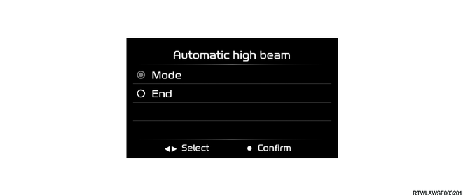
2. System operation setting
When Enable is selected by operating the MID mode switch, the automatic high beam is activated. When Disable is selected with the MID mode switch, the automatic high beam is not activated. For the automatic high beam, the previously selected set value is kept when the ignition switch is turned OFF and ON again.
MID mode switch
Legend
- MID mode L switch
- MID mode confirm switch
- MID mode R switch
Multi-Information Display
| Screen display |
Description |
||
| Automatic high beam |
Mode |
Enable |
Select when setting the automatic high beam to ON. |
| Disable |
Select when setting the automatic high beam to OFF. |
||
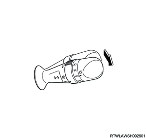
3. System activation
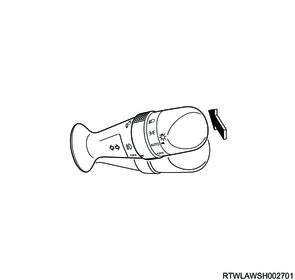
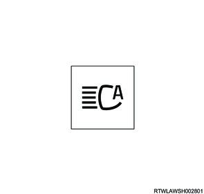
If the light control switch lever is operated to the high beam position with the light control switch in the AUTO position and the headlight illuminated, the automatic high beam is activated. The automatic high beam indicator light illuminates when the automatic high beam is activated. The automatic high beam indicator light does not illuminate because the automatic high beam is not activated if the headlights are turned OFF.
Light control switch
Automatic high beam indicator light
After the automatic high beam is activated, if the high beam switching conditions are met, the headlights are switched to the high beam, and the high beam indicator light illuminates.
High beam indicator light

Note
- Use the user customization function with the vehicle stopped. When running the vehicle during operation, the set value is reset.
4. System operation
The stereo camera recognizes the surrounding traffic conditions based on the ambient brightness, preceding vehicle taillights, and oncoming vehicle headlights detected by the right and left cameras. The stereo camera automatically switches the headlights to high beam or low beam according to the vehicle speed and traffic conditions.
Note
- If the AEB OFF indicator light illuminates, the automatic high beam is not activated.
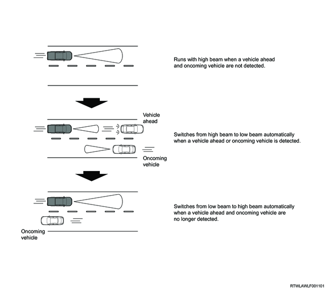
5. Automatic switching to high beam/low beam
1) Switching operation to high beam
When the automatic high beam is activated, the headlights switch to the high beam if all the following are met.
- The vehicle speed is approximately 40 km/h {25 mph} or more.
- Neither a preceding vehicle nor oncoming vehicle is detected
- There is no light-emitting object such as a streetlight in front of the own vehicle.
Note
- The automatic high beam may not operate for several seconds even if the vehicle speed exceeds the speed in the system operating conditions due to sudden acceleration.
2) Switching conditions to low beam
While the automatic high beam is activated, the headlights switch to low beam under the following.
- The vehicle speed is approximately 30 km/h {20 mph} or less.
- A preceding or oncoming vehicle is detected.
- The taillight of the preceding vehicle or the headlight of the oncoming vehicle illuminates.
- There is a light-emitting object such as a streetlight in front of the own vehicle.
6. Non-operating system conditions
Depending on the following situations, high beam may not be switched to low beam.
- An oncoming vehicle suddenly appears while the own vehicle is running on a curve with poor visibility.
- Another vehicle passes in front of the own vehicle.
- A preceding vehicle or oncoming vehicle appears in or disappears from sight due to continuous curves, a median strip, or street trees, etc.
- A preceding vehicle approaches from a far lane.
- The preceding vehicle is running without any light.
In addition, the switching timing between the high beam and the low beam may change depending on the following.
- Light color and brightness of the preceding or oncoming vehicle
- Behavior and orientation of the preceding or oncoming vehicle
- Only one headlight of the preceding vehicle or oncoming vehicle illuminates.
- A motorcycle is approaching or running ahead.
- Road conditions (road gradient, road curvature, road surface conditions, etc.)
- Number of occupants, weight of cargo
7. Manual switching to high beam/low beam
1) Switching operation to high beam
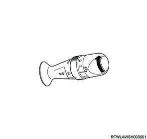
When the light control switch is turned from the AUTO position to the low beam position while the automatic high beam is in operation, the headlight switches to the high beam, the automatic high beam indicator light turns OFF, and then the high beam indicator light illuminates.
Light control switch
High beam indicator light
2) Switching operation to low beam
When the light control switch lever is operated to the original position while the automatic high beam is in operation, the headlights switch to the low beam and the automatic high beam indicator light turns OFF.
Light control switch
13. Traffic Sign Recognition (TSR)
1. Traffic sign recognition (TSR) overview
The traffic sign recognition is a system that displays the road sign information detected by the stereo camera on the multi-information display to inform a driver of the sign information during driving. When overspeed of the vehicle is detected, the driver is alerted by an alarm sounded from the instrument panel cluster and indication on the multi-information display. The system is activated when the stereo camera detects a road sign during driving.
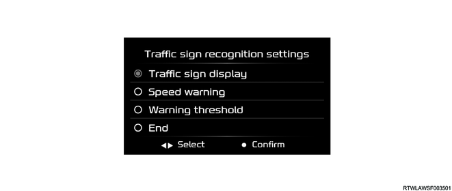
2. System operation setting
When Enable is selected by operating the MID mode switch, the traffic sign recognition is activated. When Disable is selected with the MID mode switch, the traffic sign recognition is not activated. Even if the ignition switch is turned OFF with Disable selected, the traffic sign recognition is set to Enable when the ignition switch is turned ON again.
MID mode switch
Legend
- MID mode L switch
- MID mode confirm switch
- MID mode R switch
Multi-Information Display
| Screen display |
Description |
||
| Traffic sign recognition settings |
Traffic sign display |
Enable |
Select when setting the traffic sign recognition to ON. |
| Disable*2 |
Select when setting the traffic sign recognition to OFF. |
||
| Speed warning*1 |
Visual and audible |
Select when operating the overspeed warning display using an alarm and multi-information display. |
|
| Visual only |
Select when operating the overspeed warning display using the multi-information display. |
||
| Off |
Select when setting the overspeed warning to OFF. |
||
| Warning threshold*1 |
2 km/h (1 mph) |
When the vehicle speed exceeds the speed limit indicated on the multi-information display by 2 km/h {1 mph}, the alarm will operate. |
|
| 5 km/h (3 mph) |
When the vehicle speed exceeds the speed limit indicated on the multi-information display by 5 km/h {3 mph}, the alarm will operate. |
||
| 10 km/h (6 mph) |
When the vehicle speed exceeds the speed limit indicated on the multi-information display by 10 km/h {6 mph}, the alarm will operate. |
||
| *1: Speed warning and Warning threshold can be set only when Traffic sign display is set to Enable. |
|||
| *2: When the traffic sign display is set to Disable, the speed limiter is forcibly set to manual. |
|||
Note
- Use the user customization function with the vehicle stopped. When running the vehicle during operation, the set value is reset.
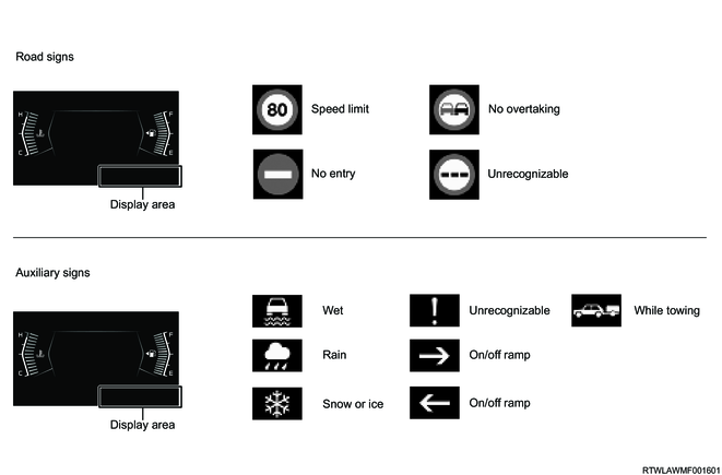
3. System operation
The stereo camera displays the road sign information detected by the right and left cameras on the multi-information display. The sign information detected by the stereo camera is displayed in the following area on the multi-information display.
Multi-Information Display
Note
- The engine is stopped with the speed limit sign indicated on the multi-information display, the engine is restarted, and then the same sign is displayed.
- Only when the following icons on the navigation bar are selected by operating the MID mode switch, up to 3 signs can be displayed on the multi-information display.
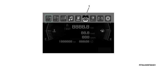
Legend
- Driving support system information display
1) Speed limit sign
If all the following are met, the speed limit sign is displayed on the multi-information display.
- The stereo camera recognizes the speed limit sign on a road sign.
- The vehicle is passing the speed limit sign, which is a detection target.
The speed limit sign indicated on the multi-information display turns OFF under the following.
- The vehicle has driven a certain mileage or more after the stereo camera detects the speed limit sign.
- The stereo camera newly detects another speed limit sign.
- The driving lane is changed in response to turning right or left.
2) Exceeding the speed limit
If the vehicle speed exceeds the speed limit detected by the stereo camera, an alarm sounds from the instrument panel cluster and the speed limit sign indicated on the multi-information display flashes (a maximum of approximately 10 seconds).
Under the following, the warning for exceeding the speed limit is canceled.
- The vehicle speed is less than the speed limit indicated on the multi-information display.
- The speed limit indicated on the multi-information display is updated and the vehicle speed becomes lower than the updated speed limit.
- The speed limit sign indicated on the multi-information display is turned OFF.
3) No entry sign
If all the following are met, the no entry sign is displayed on the multi-information display.
- The stereo camera recognizes no entry sign on a road sign.
- The vehicle is passing just before the no entry sign, which is a detection target.

Note
- If the vehicle has driven a certain mileage or more after the stereo camera detects the no entry sign, the no entry sign indicated on the multi-information display turns OFF.
4) No overtaking sign
If all the following are met, the no overtaking sign is displayed on the multi-information display.
- The stereo camera recognizes the no overtaking sign on a road sign.
- The vehicle is passing the no overtaking sign, which is a detection target.
The no overtaking sign indicated on the multi-information display turns OFF under the following.
- The vehicle has driven a certain mileage or more after the stereo camera detects the no overtaking sign.
- The driving lane is changed in response to turning right or left.
4. Non-operating system conditions
The traffic sign recognition may not be activated under the following.
- The road sign is dirty with mud, snow, etc.
- Road signs are hidden with trees, other vehicles, etc.
- The brightness of the road sign is partially different due to shadows, etc.
- The road sign is bent or distorted.
- The position of the road sign is too low or too high.
- The road sign is too large or too small.
- The road sign is too bright or too dark (electronic road sign).
- There is an abject whose color or shape is similar to the recognized road sign (similar road sign, signboard, etc.).
- The time for the stereo camera to recognize the road sign is short.
- The driving condition is incorrectly determined due to a direction change, lane change, etc.
- There is a traffic sign immediately after an expressway intersection or immediately before adjacent lanes merge into one.
- A sticker is attached to the back of the preceding vehicle.
- The speed sign on the side road enters the recognition range of the stereo camera.
- The vehicle runs on a rotary.
- An object on the instrument panel cluster reflects on the windshield.
- The vehicle is tilted due to heavy cargo, etc.
- Tire air pressure is improper.
- Special tires are installed.
- The vehicle passes through a parking exit or highway tollgate.
- A vehicle suddenly turns.
- The surrounding brightness changes suddenly (such as a tunnel entrance and exit)
- The light is weak due to dirt or misalignment of the headlights.
- A windshield is dirty or foggy.
- Water droplet is attached on the windshield or stereo camera.
- The vehicle receives strong light (back light, high beam, etc.) from the vehicle front.
- Strong light reflects from the road.
- There is a road sign in the location where headlights are difficult to reach (during night driving, in a tunnel, etc.).
- Bad weather (rain, snow, fog, etc.)
14. Intelligent Speed Limiter (ISL)
1. Intelligent speed limiter (ISL) overview
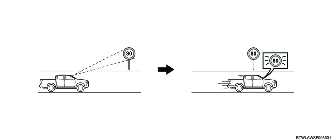
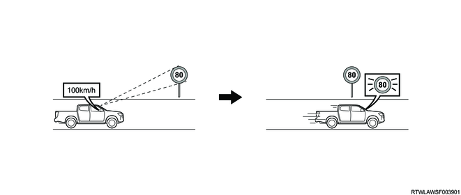
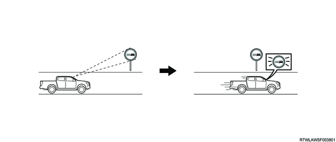
The intelligent speed limiter is a system that suppresses overspeed while the vehicle is running in the range of 30 km/h {20 mph} to 130 km/h {80 mph} based on the speed limit sign detected by the traffic sign recognition. The intelligent speed limiter allows the driver to set the vehicle speed arbitrarily, in the same manner as the manual speed limiter.
Warning
- If another driver takes over when the intelligent speed limiter is used, be sure to turn OFF the system. If the following driver does not recognize that the intelligent speed limiter is in operation, an accident may occur because the vehicle is not accelerated even if the accelerator pedal is depressed.
Note
- If the traffic sign recognition cannot be used, the intelligent speed limiter is not activated.
2. System operation setting
When Intelligent is selected by operating the MID mode switch, the intelligent speed limiter is activated. When Manual is selected by the MID mode switch, the intelligent speed limiter is not activated.
MID mode switch
Legend
- MID mode L switch
- MID mode confirm switch
- MID mode R switch
Multi-Information Display

| Screen display |
Description |
||
| Speed limiter |
Mode |
Intelligent* |
Select when activating the intelligent speed limiter. |
| Manual |
Select when activating the manual speed limiter. |
||
| *: When Speed limiter is set to Intelligent, Traffic sign display is forcibly set to Enable. |
|||
Note
- Use the user customization function with the vehicle stopped. When running the vehicle during operation, the set value is reset.
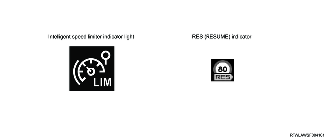
3. System activation
The intelligent speed limiter is activated by operating the main switch. When the intelligent speed limiter is activated, the intelligent speed limiter indicator light illuminates in white. When a speed limit sign is displayed on the multi-information display by the traffic sign recognition, the RES (RESUME) indicator also illuminates in white.
Automatic transmission model
Legend
- Inter-vehicular distance switch
- SET/+ switch
- Main switch
- CANCEL switch
- RES switch
- SET/- switch
Manual transmission model
Legend
- SET/- switch
- RES switch
- SET/+ switch
- Main switch
- CANCEL switch
Multi-Information Display
4. System operation
When the RES switch is pressed, the speed limit sign indicated on the multi-information display is set as the upper vehicle speed limit, and the intelligent speed limiter starts to operate. At this time, the intelligent speed limiter indicator light and RES (RESUME) indicator color switches from white to green, and only RES (RESUME) indicator turns OFF after approximately 3 seconds. If the vehicle speed exceeds the set speed by approximately 5 km/h {3 mph} or more, an alarm sounds from the instrument panel cluster and the set speed display flashes.
Note
- On a downhill slope, the vehicle speed may exceed the set speed.
5. System deactivation or cancellation
1) System deactivation
If the main switch is pressed while the intelligent speed limiter is in operation, the intelligent speed limiter is turned OFF. When the intelligent speed limiter is turned OFF, the intelligent speed limiter indicator light turns OFF.
2) System cancellation
If the CANCEL switch is pressed while the intelligent speed limiter is in operation, the intelligent speed limiter is canceled and the color of the intelligent speed limiter indicator light switches from green to white.
Note
- The intelligent speed limiter is temporally disabled by depressing the accelerator pedal firmly. When the vehicle speed becomes the set vehicle speed or less, the intelligent speed limiter is restored.
15. Manual Speed Limiter (MSL)
1. Manual speed limiter (MSL) overview
The manual speed limiter is a system that suppresses overspeed while the vehicle is running based on a vehicle speed arbitrarily set by a driver in the range of 30 km/h {20 mph} to 160 km/h {100 mph}.
Warning
- If another driver takes over when the manual speed limiter is used, be sure to turn OFF the system. If the following driver does not recognize that the manual speed limiter is in operation, an accident may occur because the vehicle is not accelerated even if the accelerator pedal is depressed.
2. System operation setting
When Manual is selected by operating the MID mode switch, the manual speed limiter is activated. When Intelligent is selected with the MID mode switch, the manual speed limiter is not activated.
MID mode switch
Legend
- MID mode L switch
- MID mode confirm switch
- MID mode R switch
Multi-Information Display
| Screen display |
Description |
||
| Speed limiter |
Mode |
Intelligent |
Select when activating the intelligent speed limiter. |
| Manual |
Select when activating the manual speed limiter. |
||
Note
- Use the user customization function with the vehicle stopped. When running the vehicle during operation, the set value is reset.
3. System activation
The manual speed limiter is activated by operating the main switch. When the manual speed limiter is activated, the manual speed limiter indicator light illuminates in white.
Automatic transmission model
Legend
- Inter-vehicular distance switch
- SET/+ switch
- Main switch
- CANCEL switch
- RES switch
- SET/- switch
Manual transmission model
Legend
- SET/- switch
- RES switch
- SET/+ switch
- Main switch
- CANCEL switch
Manual speed limiter indicator light
4. System operation
When the SET switch is pressed after setting the desired vehicle speed by operating the accelerator pedal, the manual speed limiter starts to operate. At this time, the manual speed limiter indicator light color switches from white to green. If the vehicle speed exceeds the set speed by approximately 5 km/h {3 mph} or more, an alarm sounds from the instrument panel cluster and the set speed display flashes.
Note
- On a downhill slope, the vehicle speed may exceed the set speed.
5. System deactivation or cancellation
1) System deactivation
If the main switch is pressed while the manual speed limiter is in operation, the manual speed limiter is turned OFF. When the manual speed limiter is turned OFF, the manual speed limiter indicator light turns OFF.
2) System cancellation
If the CANCEL switch is pressed while the manual speed limiter is in operation, the manual speed limiter is canceled and the color of the manual speed limiter indicator light switches from green to white.
Note
- The manual speed limiter is temporally disabled by depressing the accelerator pedal firmly. When the vehicle speed becomes the set vehicle speed or less, the manual speed limiter is restored.
6. Setting and changing of vehicle speed
1) Acceleration of vehicle speed
The vehicle speed indicated on the multi-information display changes while the SET/+ switch is pressed. When the switch is short pressed, the vehicle speed increases by 1 km/h {1 mph} and when it is long pressed, the speed increases by 5 km/h {5 mph}. When releasing the SET/+ switch at the desired vehicle speed, the vehicle speed is set as the desired one.
2) Deceleration of vehicle speed
The vehicle speed indicated on the multi-information display changes while the SET/- switch is pressed. When the switch is short pressed, the vehicle speed decreases by 1 km/h {1 mph} and when it is long pressed, the speed decreases by 5 km/h {5 mph}. When releasing the SET/- switch at the desired vehicle speed, the vehicle speed is set as the desired one.
16. Stereo camera system components
1. Stereo camera
The stereo camera is installed on the upper part of the windshield, and consist of the right and left cameras, an image processing part, recognition part, and control part. The stereo camera detects and recognizes a vehicle, pedestrian, bicycle, obstacle, lane, illuminant, sign, etc., in front of the own vehicle. The stereo camera activates each function based on the recognized information and current vehicle information.
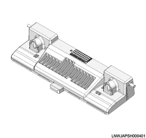
2. Steering angle sensor
The steering angle sensor is installed to the combination switch and it detects the steering speed and steering angle. The signal detected by the steering angle sensor is sent to the stereo camera via the CAN communication circuit.

Legend
- Steering angle sensor
- Combination switch
3. ECM
The ECM sends the engine speed, accelerator opening position, vehicle speed, engine torque, etc., to the stereo camera via the CAN communication circuit. Also, the ECM processes torque request signals and torque cut request signals sent from the stereo camera, and controls fuel injection.
4JJ3 engine models
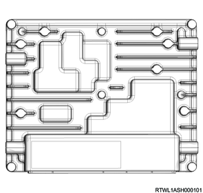
RZ4E-TC engine models
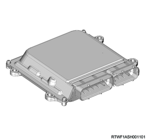
4. TCM
The TCM sends the gear position, etc., to the stereo camera via the CAN communication circuit. Also, the TCM performs the shift control according to the vehicle speed while driving with adaptive cruise control.
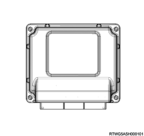
5. EHCU
The EHCU receives brake operation request signals and retention request signals from the stereo camera via the CAN communication circuit. The EHCU operates the brake with the requested deceleration based on the received information.
Note
- If the vehicle posture becomes unstable because of the AEB operation, the ESC function is prioritized over the brake operation request.
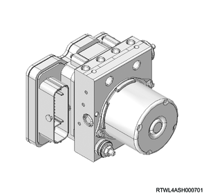
6. EPS motor control unit
The EPS motor control unit sends the steering torque, etc., to the stereo camera via the CAN communication circuit. Also, when receiving steering torque request signals from the stereo camera, the EPS motor control unit performs the steering control based on the requested torque.

Legend
- EPS motor control unit
7. BCM
The BCM sends the various switch information, etc., to the stereo camera via the CAN communication circuit. Also, when the BCM receives headlight switching request signals from the stereo camera, the BCM switches the headlights to low beam or high beam.
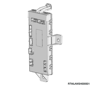
8. Radar sensor
The radar sensor sends the BSM object detection information to the stereo camera via the CAN communication circuit. The stereo camera controls the emergency lane keeping based on the BSM object detection information received from the radar sensor.
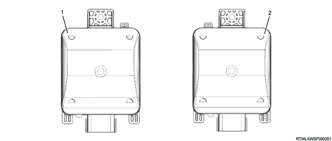
Legend
- Radar sensor (Left)
- Radar sensor (Right)
9. Forward collision warning light
The forward collision warning is an indicator light that flashes under the following and is projected on the windshield by the head-up display.
- The forward collision warning is activated.
- The automatic brake by the AEB is activated.
- The pedal misapplication mitigation is activated.
- The own vehicle approaches the preceding vehicle too close while running with the adaptive cruise control.
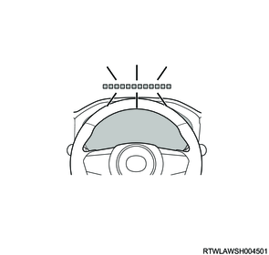
10. Instrument panel cluster
The instrument panel cluster sends the ON/OFF information, setting value, etc., of each function to the stereo camera via the CAN communication circuit. Also, if a malfunction occurs in the stereo camera system, each indicator light and master warning light are illuminated in the instrument panel cluster, and the warning is displayed on the multi-information display.
1) LDW OFF indicator light
By operating the MID mode switch, the LDW OFF indicator light illuminates when both the lane departure warning and the lane departure prevention are set to OFF (models with EPS), and it illuminates when the lane departure warning is set to OFF (models without EPS). Also, if a malfunction occurs in the related system, the LDW OFF indicator light illuminates.
2) ELK OFF indicator light
The ELK OFF indicator light illuminates when the emergency lane keeping is set to OFF by operating the MID mode switch. In addition, if a malfunction occurs in the related system, the ELK OFF indicator light illuminates.

3) AEB OFF indicator light
The AEB OFF indicator light illuminates when the AEB and pedal misapplication mitigation are set to OFF by operating the MID mode switch. In addition, if a malfunction occurs in the related system, the AEB OFF indicator light illuminates.
4) Master warning light
The master warning light illuminates under the following.
- A malfunction occurs in the stereo camera.
- The temperature of the stereo camera body is excessively high or excessively low.
- The stereo camera installation shifts significantly.
- A communication malfunction occurs between the related modules.
- The battery power supplied to the stereo camera is cut off.
- The stereo camera learning is not performed.
- The stereo camera programming is not performed.
- A malfunction occurs in the forward collision warning light
5) Camera failure
If a malfunction occurs in the stereo camera, the stereo camera function is deactivated. At this time, "Front camera malfunction service required" is displayed on the multi-information display for approximately 5 seconds. The warning screen will be displayed approximately every 3 minutes unless the stereo camera function resumes.
Note
- When "Front camera malfunction service required" is displayed on the multi-information display, the master warning light, LDW OFF indicator light, ELK OFF indicator light, and AEB OFF indicator light illuminate at the same time.
6) Camera temperature
If the temperature of the stereo camera is temporarily high or low, the stereo camera function is temporarily deactivated. At this time, "Front camera temperature" is displayed on the multi-information display for approximately 5 seconds. The warning screen will be displayed approximately every 3 minutes unless the stereo camera function resumes.

Note
- "Front camera unavailable temperature" turns OFF when the stereo camera temperature returns to the normal temperature range.
- When "Front camera unavailable temperature" is displayed on the multi-information display, the LDW OFF indicator light, ELK OFF indicator light, and AEB OFF indicator light illuminate at the same time.
7) Camera low visibility
If any of the following is met, the stereo camera is deactivated temporarily. At this time, "Front camera unavailable clean windshield" is displayed on the multi-information display for approximately 5 seconds. The warning screen will be displayed approximately every 3 minutes unless the stereo camera function resumes.
- The area around the stereo camera is covered with dirt, water vapor, fog, water drops, ice, etc.
- Bad weather (such as heavy rain, snow, or fog)
- There is strong sunlight or reflection from the road surface.
- The road surface is covered with ice or snow and sunlight is reflected on the stereo camera.

Note
- When "Front camera unavailable clean windshield" is displayed on the multi-information display, the LDW OFF indicator light, ELK OFF indicator light, and AEB OFF indicator light illuminate at the same time.
8) Camera unavailable
If any of the following is met, the stereo camera is deactivated temporarily. At this time, "Front camera unavailable" is displayed on the multi-information display for approximately 5 seconds. The warning screen will be displayed approximately every 3 minutes unless the stereo camera function resumes.
- The vehicle posture changes significantly, for example, due to loading or unloading.
- The automatic adjustment of the stereo camera is insufficient.
- The AEB is activated 3 times after the engine is started.
- A malfunction occurs in the related system.
- The battery voltage is temporarily abnormal.

Note
- When "Front camera unavailable" is displayed on the multi-information display, the LDW OFF indicator light, ELK OFF indicator light, and AEB OFF indicator light illuminate at the same time.
9) Alarm sound
The following alarm sounds from the instrument panel cluster when the system is activated.
| System |
Alarm sound |
Alarm condition |
| Lane Departure Warning (LDW) |
Short repeated beeps* |
The vehicle departs from its lane. |
| Lane Departure Prevention (LDP) |
Short repeated beeps |
The steering wheel has not been operated or has not been held for a predetermined period of time |
| Emergency Lane Keeping (ELK) |
Short repeated beeps |
The vehicle changes the lane during the BSM operation. |
| Lane Keep Assist System (LKAS) |
Short repeated beeps |
The driver does not hold the steering wheel firmly for 20 seconds or more during the LKAS control. |
| Rapidly repeated beeps |
The driver does not hold the steering wheel firmly for 25 seconds or more during the LKAS control. |
|
| Attention Assist |
Short repeated beeps |
The vehicle is wandering. |
| Forward collision warning (FCW) |
Short repeated beeps |
The own vehicle approaches an obstacle ahead that may be cause a collision. |
| Autonomous Emergency Braking (AEB) |
Rapidly repeated beeps |
The driver's preventive operation is not performed even though the own vehicle approaches an obstacle ahead that may cause a collision. |
| Pedal Misapplication Mitigation |
Short repeated beeps |
The accelerator pedal is depressed more than necessary while the own vehicle recognizes an obstacle ahead. |
| Cruise Control |
Short beep |
The control is canceled by an operation other than driver's intentional operation. |
| Adaptive Cruise Control (ACC) |
||
| Short repeated beeps |
The own vehicle approaches the preceding vehicle too close while following it. |
|
| Traffic Sign Recognition (TSR) |
Short beep |
The own vehicle speed is higher than the sum of the detected speed limit and the set overspeed. |
| Intelligent speed limiter (ISL) |
Short repeated beeps |
The own vehicle speed exceeds the set vehicle speed by approximately 5 km/h (3 mph) or more. |
| Manual Speed Limiter (MSL) |
||
| *: Only for models without EPS, an alarm sounds from the instrument panel cluster. |
||
17. Stereo camera system components views
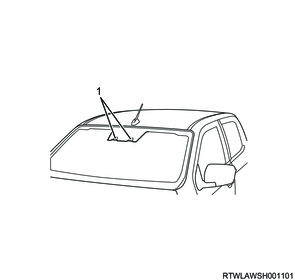
Legend
- Stereo camera
18. General circuit diagram
1. Stereo camera general circuit diagram

2. Stereo camera outline view and connector pin layout
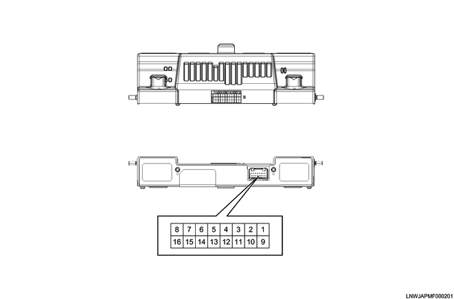
| Pin No. |
Pin function |
| 1 |
Battery power supply |
| 2 |
- |
| 3 |
- |
| 4 |
Ground |
| 5 |
- |
| 6 |
- |
| 7 |
CAN (Low) |
| 8 |
CAN (High) |
| 9 |
Ignition power supply |
| 10 |
- |
| 11 |
- |
| 12 |
Ground |
| 13 |
- |
| 14 |
- |
| 15 |
- |
| 16 |
- |