1. Introduction to the trouble diagnosis of stereo camera system
1. Overview of system diagnostic method
The system diagnostic method is a standardized method for repairing all electrical/electronic (E/E) systems. Failures in E/E systems differ from regular vehicle failures and often occur in the following steps.
1) Initial stage of failure
The failure occurs sporadically and for a short time, and often the customer does not notice it. At this stage, the customer's complaint is unclear, and the malfunction cannot be reproduced. However, the control unit may have stored the failure. (Past malfunctions)
2) Intermediate stage of failure
The failure occurs sporadically and for a short time, but may occur repeatedly at intervals, and invariably occurs under specific conditions. The customer's complaint and failure content are clear, but the failure conditions are unclear. Therefore, the person performing diagnosis on the vehicle can reproduce the failure by understanding its conditions. (Intermittent conditions)
3) Stage where failure is realistic
The failure occurs regularly, and the customer's complaint is realistic and clear. Therefore, the person performing diagnosis on the vehicle can reproduce the failure. However, there may sometimes be multiple causes for the failure. (Current malfunctions)
2. System diagnostic method
The diagnostic procedure is always used to solve problems with E/E systems and is the starting point when a repair is required. The following steps indicate how to proceed through the diagnosis.
1) Verify the customer's complaint.
In order to verify the customer's complaint, it is necessary to know how the system normally operates.
2) Perform a preliminary inspection.
- Overall visual inspection
- Maintenance history review
- Detection of abnormal noise and odor
- Collection of DTCs and system data using a scan tool
3) Check for related Service Bulletins.
Check Service Bulletins, maintenance manuals, etc.
3. If a DTC is set
Perform the repair accurately according to the specified DTC diagnosis.
4. If no DTC is set
Refer to Diagnosis by symptom, and inspect.
5. If there are no applicable symptoms
- Investigate the complaint in detail.
- Create a diagnosis plan.
- Check the operation principles based on the wiring diagram and maintenance information.
When repair history for similar cases is available, request technical assistance. Check again for related Service Bulletins.
6. If the condition is intermittent
Failures that do not always appear are referred to as being intermittent. Perform the following in order to resolve intermittent conditions.
- Check the DTC and system data.
- Verify the symptoms and conditions described by the customer.
- Use a check sheet or another method to check the circuits or electrical system components.
7. If no failures are detected
This situation indicates that the vehicle is operating normally. The condition reported by the customer may be normal. Check the customer complaint by comparing to another vehicle that is operating normally. However, depending on the condition, it may be an intermittent condition. Before returning the vehicle, check the complaint under the conditions given by the customer.
1) Investigate the complaint again.
If the complaint cannot be adequately detected or determined, it is necessary to perform the diagnosis again to verify the complaint. As stated above in regard to intermittent conditions, the complaint may be intermittent or may be a normal condition.
2) Perform the operation verification.
Check that the vehicle is operating normally and that the symptom has been corrected. This includes a road test and other methods to verify that the complaint has been resolved under the following conditions.
- Test under the conditions given by the customer.
- If a DTC was set, verify that the malfunction has been repaired by duplicating the conditions when the DTC was set while observing the scan tool data.
8. Vehicle repair verification
After repairing the electronic control system, it is necessary to verify that the repair was accurate after repairing the vehicle. If this verification is not adequate, the problems may occur again when the vehicle is returned to the customer. It is necessary to reproduce and verify the conditions of the customer complaint, especially in the case of intermittent conditions.
| Item |
Item |
Objective |
Method |
| 1 |
DTC check |
To verify repair completion |
Clear the previous DTCs. Sufficiently warm up the engine at idle, and then perform a test run to ensure the test conditions. |
| 2 |
Data list check |
To check the communication status |
Observe the data display on the scan tool. |
| 3 |
Powerful electromagnetic transmitter verification (Refer to the following supplements.) |
To verify that no interfering waves are being emitted if electromagnetic transmitters such as a transceiver are added to the vehicle |
Check whether turning an electromagnetic transmitter such as a transceiver ON/OFF changes the control unit control. If a malfunction is found, let the customer know that the installation position and output of the electromagnetic transmitter need to be changed. |
Note
- Regarding powerful electromagnetic transmitter verification
If a malfunction is detected in this item, convey the following check items to the customer as necessary.
- Install the antenna in a location as far away as possible from the vehicle electronic systems such as the control units and sensors.
- Install the antenna cord at least 20 cm {0.66 ft} or more away from the vehicle electronic systems, such as the control units and sensors.
- Do not place the antenna cord with other wiring.
- Place the antenna cord as far away from other wiring as possible.
- Make sure to install aftermarket components in accordance with their respective installation manuals.
- Do not install high-output mobile communication devices.
Caution
- Follow the following steps when verifying the repair. Failure to follow these steps may result in unnecessary repairs.
1) Review the scan tool data relating to the diagnosed DTC and make a record.
2) Clear the DTC.
3) Operate the vehicle while observing the related scan tool data.
9. Non-OEM parts
All systems are adjusted to operate with genuine parts. Therefore, if a general aftermarket sensor or switch, etc., is installed, it may make a false diagnosis.
Aftermarket electronics, such as mobile phones, stereos, and anti-theft devices, may emit electromagnetic interference into the control system if improperly installed. As a result, abnormal signals occur and cause a false diagnosis. Before performing trouble diagnoses, either turn OFF the power to aftermarket parts or remove them.
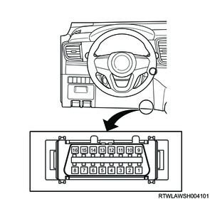
10. DLC
The DLC is installed at the following position.
RHD models
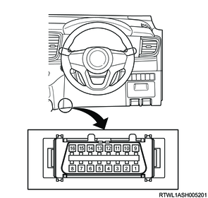
LHD models
2. Diagnostic trouble codes (DTCs)
When a malfunction is found in a system, it is recorded in the stereo camera memory. Each time the ignition switch is turned ON, the stereo camera performs a self-test for most wiring and components.
1. DTC display
Current and past DTCs stored in the stereo camera can be observed on the scan tool.
2. DTC clearing
A DTC cannot be cleared without using a scan tool.