1. Component views
Idle gear
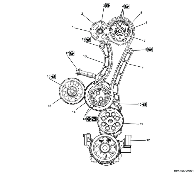
Part name
- Cam angle sensor rotor
- Inlet camshaft gear
- Bolt
- Bolt
- Timing chain
- Exhaust camshaft gear
- Camshaft sprocket
- Bolt
- Timing chain guide
- Bolt
- Crank gear
- Oil pump
- Bolt
- Idle gear A
- Supply pump gear
- Nut
- Timing chain tensioner
- Timing chain tension lever
- Bolt
Tightening torque
3: 25 N・m { 2.5 kgf・m / 18 lb・ft }
4: 25 N・m { 2.5 kgf・m / 18 lb・ft }
8: 25 N・m { 2.5 kgf・m / 18 lb・ft }
10: 25 N・m { 2.5 kgf・m / 18 lb・ft }
13: 32 N・m { 3.3 kgf・m / 24 lb・ft }
16: 64 N・m { 6.5 kgf・m / 47 lb・ft }
17: 70 N・m { 7.1 kgf・m / 52 lb・ft }
19: 25 N・m { 2.5 kgf・m / 18 lb・ft }
2. Timing chain removal
3. Idle gear removal
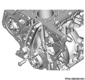
1) Remove the timing chain guide from the cylinder block.
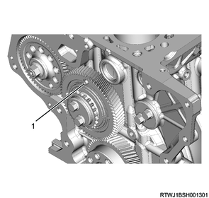
2) Apply the dial gauge to the idle gear tooth to be measured, and gently move the gear left and right to measure the fluctuation of the dial gauge.
Note
- If the measured value exceeds the limit, replace the idle gear.
Standard: 0.10 to 0.17 mm { 0.0039 to 0.0067 in }
Limit: 0.30 mm { 0.0118 in }
3) Measure the idle gear axial direction clearance using a feeler gauge.
Note
- Replace the idle gear or thrust collar if the measured value exceeds the limit.
Standard: 0.060 to 0.135 mm { 0.0024 to 0.0053 in }
Limit: 0.20 mm { 0.0079 in }
4) Install the M5 bolts for securing the sub gear to idle gear A.
Legend
- M5 bolt
5) Remove the flange from idle gear A.
6) Remove idle gear A from the idle gear A shaft.
7) Remove the idle gear A shaft from the cylinder block.
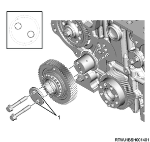
Legend
- Front mark