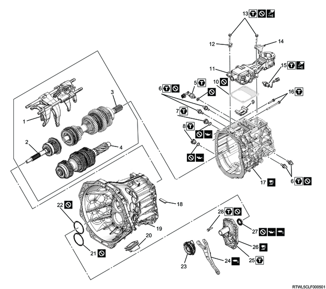
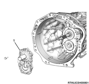
1. Component views
Transmission (RZ4E, 2WD models)

Part name
- Shift rod and shift fork
- Input shaft
- Main shaft
- Counter shaft
- Backup light switch
- Detent plug
- Filler plug
- Drain plug
- Interlock plate
- Gasket
- Control box
- Harness bracket
- Bolt
- Harness bracket
- Neutral switch
- Bolt
- Speedometer driven gear (Models without ABS)
- Rear case
- Magnet
- Clutch housing
- Boot
- Counter shaft front bearing outer snap ring
- Input shaft front bearing outer snap ring
- Release bearing
- Shift fork
- Shift fork support
- Front cover
- Front oil seal
- Bolt
Tightening torque
5: 39 N・m { 4.0 kgf・m / 29 lb・ft }
6: 30 N・m { 3.1 kgf・m / 22 lb・ft }
7: 39 N・m { 4.0 kgf・m / 29 lb・ft }
8: 39 N・m { 4.0 kgf・m / 29 lb・ft }
13: 19 N・m { 1.9 kgf・m / 14 lb・ft }
15: 39 N・m { 4.0 kgf・m / 29 lb・ft }
16: 23 N・m { 2.3 kgf・m / 17 lb・ft }
26: 39.2 N・m { 4.0 kgf・m / 29 lb・ft }
29: 19 N・m { 1.9 kgf・m / 14 lb・ft }
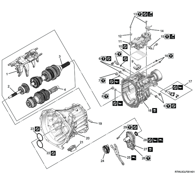
Transmission (RZ4E, 4WD models)
Part name
- Shift rod and shift fork
- Input shaft
- Main shaft
- Counter shaft
- Backup light switch
- Detent plug
- Filler plug
- Drain plug
- Interlock plate
- Gasket
- Control box
- Harness bracket
- Bolt
- Harness bracket
- Neutral switch
- Bolt
- Rear case
- Magnet
- Clutch housing
- Boot
- Counter shaft front bearing outer snap ring
- Input shaft front bearing outer snap ring
- Release bearing
- Shift fork
- Shift fork support
- Front cover
- Front oil seal
- Bolt
Tightening torque
5: 39 N・m { 4.0 kgf・m / 29 lb・ft }
6: 30 N・m { 3.1 kgf・m / 22 lb・ft }
7: 39 N・m { 4.0 kgf・m / 29 lb・ft }
8: 39 N・m { 4.0 kgf・m / 29 lb・ft }
13: 19 N・m { 1.9 kgf・m / 14 lb・ft }
15: 39 N・m { 4.0 kgf・m / 29 lb・ft }
16: 23 N・m { 2.3 kgf・m / 17 lb・ft }
25: 39.2 N・m { 4.0 kgf・m / 29 lb・ft }
28: 19 N・m { 1.9 kgf・m / 14 lb・ft }
Transmission (4JJ3, 2WD models)
Part name
- Shift rod and shift fork
- Input shaft
- Main shaft
- Counter shaft
- Backup light switch
- Detent plug
- Filler plug
- Drain plug
- Interlock plate
- Gasket
- Control box
- Harness bracket
- Bolt
- Harness bracket
- Neutral switch
- Bolt
- Speedometer driven gear (Models without ABS)
- Rear case
- Magnet
- Clutch housing
- Boot
- Counter shaft front bearing outer snap ring
- Input shaft front bearing outer snap ring
- Release bearing
- Shift fork
- Shift fork support
- Front cover
- Front oil seal
- Bolt
Tightening torque
5: 39 N・m { 4.0 kgf・m / 29 lb・ft }
6: 30 N・m { 3.1 kgf・m / 22 lb・ft }
7: 39 N・m { 4.0 kgf・m / 29 lb・ft }
8: 39 N・m { 4.0 kgf・m / 29 lb・ft }
13: 19 N・m { 1.9 kgf・m / 14 lb・ft }
15: 39 N・m { 4.0 kgf・m / 29 lb・ft }
16: 23 N・m { 2.3 kgf・m / 17 lb・ft }
26: 39.2 N・m { 4.0 kgf・m / 29 lb・ft }
29: 19 N・m { 1.9 kgf・m / 14 lb・ft }
Transmission (4JJ3, 4WD models)

Part name
- Shift rod and shift fork
- Input shaft
- Main shaft
- Counter shaft
- Backup light switch
- Detent plug
- Filler plug
- Drain plug
- Interlock plate
- Gasket
- Control box
- Harness bracket
- Bolt
- Harness bracket
- Neutral switch
- Bolt
- Rear case
- Magnet
- Clutch housing
- Boot
- Counter shaft front bearing outer snap ring
- Input shaft front bearing outer snap ring
- Release bearing
- Shift fork
- Shift fork support
- Front cover
- Front oil seal
- Bolt
Tightening torque
5: 39 N・m { 4.0 kgf・m / 29 lb・ft }
6: 30 N・m { 3.1 kgf・m / 22 lb・ft }
7: 39 N・m { 4.0 kgf・m / 29 lb・ft }
8: 39 N・m { 4.0 kgf・m / 29 lb・ft }
13: 19 N・m { 1.9 kgf・m / 14 lb・ft }
15: 39 N・m { 4.0 kgf・m / 29 lb・ft }
16: 23 N・m { 2.3 kgf・m / 17 lb・ft }
25: 39.2 N・m { 4.0 kgf・m / 29 lb・ft }
28: 19 N・m { 1.9 kgf・m / 14 lb・ft }
2. Shift rod reassembly
1) Install the 5th - 6th shift arm to the reverse and 5th - 6th shift rod.
Note
- The shift rod has no front or rear directions.
- The shift rod has no up or down directions.
2) Press-fit the spring pin until it is flush with the 5th - 6th shift arm.
Caution
- Do not reuse the spring pin.
3) Install the 5th - 6th shift block to the reverse and 5th - 6th shift rod.
Caution
- Install the 5th - 6th shift block as shown in the diagram.
4) Press-fit the spring pin until it is flush with the 5th - 6th shift block.
Caution
- Do not reuse the spring pin.
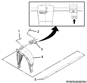
Legend
- Spring pin
- Spring pin
- 5th - 6th shift block
- 5th - 6th shift arm
- Reverse and 5th - 6th shift rod
5) Install the reverse shift arm to the reverse and 5th - 6th shift rod.
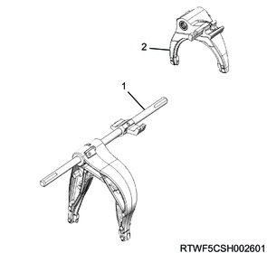
Legend
- Reverse and 5th - 6th shift rod
- Reverse shift arm
6) Install the 3rd - 4th shift arm to the 1st - 2nd and 3rd - 4th shift rod.
Note
- The shift rod has no front or rear directions.
- The shift rod has no up or down directions.
7) Press-fit the spring pin until it is flush with the 3rd - 4th shift arm.
Caution
- Do not reuse the spring pin.

Legend
- 1st - 2nd and 3rd - 4th shift rod
- Spring pin
- 3rd - 4th shift arm
8) Install the 1st - 2nd shift arm to the 1st - 2nd and 3rd - 4th shift rod.
9) Install the 3rd - 4th shift block to the 1st - 2nd and 3rd - 4th shift rod.
10) Press-fit the spring pin until it is flush with the 3rd - 4th shift block.
Caution
- Do not reuse the spring pin.
Legend
- 3rd - 4th shift arm
- 1st - 2nd and 3rd - 4th shift rod
- Spring pin
- 3rd - 4th shift block
- 1st - 2nd shift arm
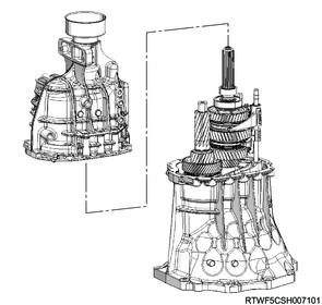
3. Main shaft installation
1) Place the clutch housing on its front side.
2) Engage the 1st - 2nd synchronizer sleeve with the 2nd gear.
3) Engage the 3rd - 4th synchronizer sleeve with the 3rd gear.
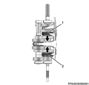
- 1st - 2nd synchronizer sleeve
- 3rd - 4th synchronizer sleeve
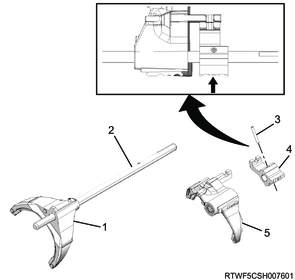
4) Install the special tool between the 1st - 2nd shift arm and the 3rd - 4th shift block using a string.
Caution
- Remove the special tool after installing the front cover.
- Firmly secure with the string to prevent the special tool position from getting out of alignment.

SST: 5-8840-3251-0 - holding fixture
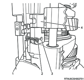
- 1st - 2nd shift arm
- String
- 5-8840-3251-0
- 3rd - 4th shift block
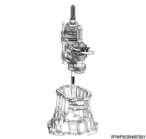
5) Install the following parts as a set to the clutch housing.
- Input shaft
- Main shaft
- Counter shaft
- Each shift arm and shift rod
4. Rear case installation
1) Apply ThreeBond TB1215 or equivalent to the rear case mating surface.
Note
- Apply to the specified marked area shown in the diagram.
Caution
- Before applying, remove any water and oil from the connecting surface. Then apply one continuous bead with a diameter of 2 mm {0.08 in} or more around the entire circumference.

Note
- Set the main shaft rear bearing outer snap ring on the rear case beforehand.
Caution
- Do not reuse the snap ring.
2) While widening the snap ring inside edge with snap ring pliers, align the input shaft, counter shaft, and shift rod positions with the rear case, and insert.
Note
- At this point, the snap ring does not fit in the groove because the main shaft is falling.
Legend
- Snap ring inside edge
- Snap ring
3) Install the rear case to the clutch housing.
Tightening torque: 23 N・m { 2.3 kgf・m / 17 lb・ft }
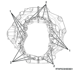
Legend
- M8 x 1.25 x 100 mm
- M8 x 1.25 x 40 mm
5. Backup light switch installation
1) Install the backup light switch and gasket to the rear case.
Caution
- Do not reuse the gasket.
Tightening torque: 39 N・m { 4.0 kgf・m / 29 lb・ft }
6. Speedometer driven gear installation
1. 2WD models (Models without ABS)
1) Apply engine oil to the O-ring surface.
2) Install the O-ring to the speedometer bushing.
Caution
- Do not reuse the O-ring.
3) Install the speedometer bushing to the speedometer driven gear.
4) Install the speedometer driven gear to the rear case.
Tightening torque: 15 N・m { 1.5 kgf・m / 11 lb・ft }
7. Front cover installation
1. RZ4E
1) Install the input shaft bearing snap ring to the input shaft using snap ring pliers.
Caution
- Do not reuse the input shaft bearing snap ring.
2) Install the counter front bearing snap ring to the counter shaft using snap ring pliers.
Caution
- Do not reuse the counter front bearing snap ring.
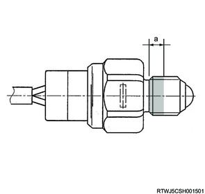
3) Install the front oil seal to the front cover.
4) Apply the recommended lubricating oil to the outer circumference of the front oil seal.
Note
- Press-fit the front oil seal to the specified position using the special tool.
Standard: 1.0 to 2.0 mm { 0.039 to 0.079 in }
SST: 5-8840-3161-0 - oil seal installer
Legend
- 5-8840-3161-0
- Front oil seal
Standard value
a: 1.0 to 2.0 mm { 0.039 to 0.079 in }
5) Apply BESCO L-2 grease or equivalent to the lip section.
6) Push the input shaft and counter shaft to rear side, and fit the main shaft rear bearing outer snap ring in the bearing groove.
7) Apply ThreeBond TB1215 or equivalent to the front cover mating surface.
Caution
- Before applying, remove any water and oil from the connecting surface. Then apply one continuous bead with a diameter of 2 mm {0.08 in} or more around the entire circumference.
- Pay attention not to block the oil groove by excessively applying ThreeBond TB1215 or equivalent to the front cover.

8) Install the front cover to the transmission case.
Caution
- Do not reuse the front cover mounting bolts.
Tightening torque: 19 N・m { 1.9 kgf・m / 14 lb・ft }
Legend
- Front cover
9) Remove the special tool from between the 1st - 2nd shift arm and the 3rd - 4th shift block.
Note
- Return the shift position to neutral.
- 3rd - 4th shift block
- 5-8840-3251-0
- 1st - 2nd shift arm
2. 4JJ3
1) Install the input shaft bearing snap ring to the input shaft using snap ring pliers.
Caution
- Do not reuse the input shaft bearing snap ring.
2) Install the counter front bearing snap ring to the counter shaft using snap ring pliers.
Caution
- Do not reuse the counter front bearing snap ring.
3) Install the front oil seal to the front cover.
4) Apply the recommended lubricating oil to the outer circumference of the front oil seal.
Note
- Press-fit the front oil seal to the specified position using the special tool.
Standard: 1.0 to 2.0 mm { 0.039 to 0.079 in }
SST: 5-8840-3262-0 - oil seal installer
Legend
- 5-8840-3262-0
- Front oil seal
Standard value
a: 1.0 to 2.0 mm { 0.039 to 0.079 in }
5) Apply BESCO L-2 grease or equivalent to the lip section.
6) Push the input shaft and counter shaft to rear side, and fit the main shaft rear bearing outer snap ring in the bearing groove.
7) Apply ThreeBond TB1215 or equivalent to the front cover mating surface.
Caution
- Before applying, remove any water and oil from the connecting surface. Then apply one continuous bead with a diameter of 2 mm {0.08 in} or more around the entire circumference.
- Pay attention not to block the oil groove by excessively applying ThreeBond TB1215 or equivalent to the front cover.
8) Install the front cover to the transmission case.
Caution
- Do not reuse the front cover mounting bolts.
Tightening torque: 19 N・m { 1.9 kgf・m / 14 lb・ft }
Legend
- Front cover
9) Remove the special tool from between the 1st - 2nd shift arm and the 3rd - 4th shift block.
Note
- Return the shift position to neutral.
- 3rd - 4th shift block
- 5-8840-3251-0
- 1st - 2nd shift arm
8. Detent installation
1) Readjust the transmission position to the direction shown in the diagram.

2) Install the detent to the rear case.
Caution
- Do not reuse the detent.
Tightening torque: 30 N・m { 3.1 kgf・m / 22 lb・ft }
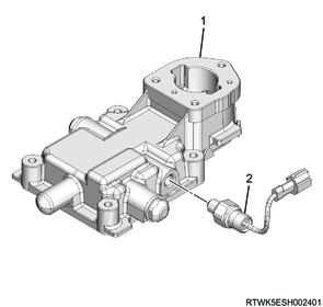
9. Control box installation
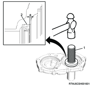
1) Install the neutral switch to the control box.
Note
- Completely remove any sealing agent on the threaded portion, then apply ThreeBond 1141 or equivalent to the specified area of the neutral switch threaded portion.
- The application area of liquid gasket must be less than half the length of the threaded portion.
Legend
a. Liquid gasket application area
Tightening torque: 39 N・m { 4.0 kgf・m / 29 lb・ft }
RZ4E

Legend
- Control box
- Neutral switch
4JJ3
Legend
- Control box
- Neutral switch
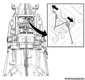
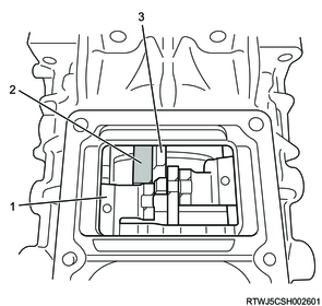
2) Install the interlock plate to the rear case.
Caution
- Install the interlock plate in the direction shown in the diagram.

Legend
- Interlock plate
3) Install the control box and gasket to the transmission.
Caution
- Do not reuse the gasket.

Note
- Install the harness bracket together with the control box as shown in the diagram.
Caution
- Do not reuse the control box mounting bolts.
Tightening torque: 19 N・m { 1.9 kgf・m / 14 lb・ft }
RZ4E

Legend
- Harness bracket
Standard value
a: 5 ° or less
4JJ3

Legend
- Harness bracket
Standard value
a: 5 ° or less
10. Shift fork installation
1) Install the shift fork and boot to the transmission case.
2) Install the release bearing and spring as a set to the transmission case.