1. ICR relay inspection
1. Visual inspection
1) Inspect the ICR relay for the following.
- Cracking
- Damage
Note
- Replace the ICR relay if a malfunction is found.
2. Output inspection
1) Referring to the diagram, connect the inspection wiring to the ICR relay.
Caution
- Do not mistake the connection position of the wiring.
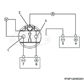
Legend
- M-terminal
- S-terminal
- B-terminal
- Rated voltage (Positive side)
- Rated voltage (Negative side)
- Rated current (Positive side)
- Rated current (Negative side)
2) Inspect the output waveforms between the B-terminal and the M-terminal, and the S-terminal of the ICR relay using an oscilloscope when the following conditions are met.
- Energize current between the B-terminal and the M-terminal.
- Apply voltage to between the S-terminal and the ground.
Standard: 50 A Rated current
Standard: 12 V Rated voltage
Caution
- Current energization and voltage application should be stopped within 5 seconds.
Standard: 0.45 to 0.55 V Voltage 1
Standard: 0.05 V or less Voltage 2
Standard: 5 A or less Current 1
Standard value: 108 to 132 ms Time 1
Voltage between B-terminal and M-terminal
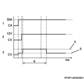
Legend
- Current between B-terminal and M-terminal (50 A)
- S-terminal voltage (12 V)
- Voltage between B-terminal and M-terminal
- Voltage 1
- Voltage 2
- Time 1
S-terminal current
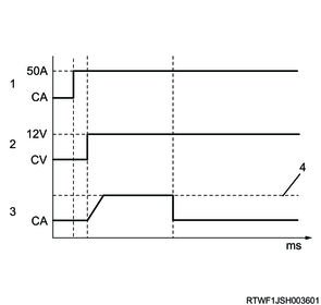
Legend
- Current between B-terminal and M-terminal (50 A)
- S-terminal voltage (12 V)
- S-terminal current
- Current 1