1. Component views
Front disc brake
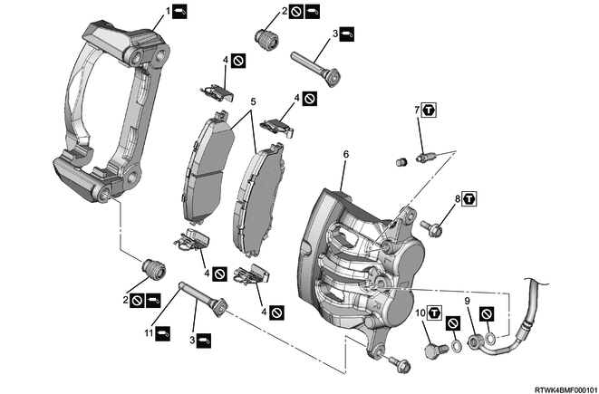
Part name
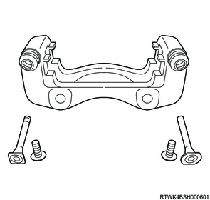
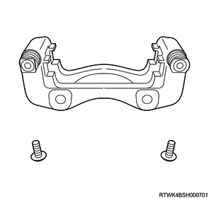
- Brake support
- Boot
- Slide pin (Lock pin and guide pin)
- Pad clip
- Brake pad (With shim)
- Brake caliper
- Breeder bolt
- Lock bolt
- Brake hose
- Bolt
- Pin bushing
Tightening torque
7: 9 to 13 N・m { 0.9 to 1.3 kgf・m / 80 to 115 lb・in }
8: 32 to 42 N・m { 3.3 to 4.3 kgf・m / 24 to 31 lb・ft }
10: 29 to 39 N・m { 3.0 to 4.0 kgf・m / 21 to 29 lb・ft }
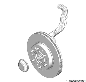
2. Front hub installation
1. 2WD (Except high ride suspension specifications)
1) Install the knuckle cap to the knuckle.
2) Install the front hub and brake rotor to the knuckle.
3) Install the bolt to the knuckle.
Tightening torque: 85 N・m { 8.7 kgf・m / 63 lb・ft }
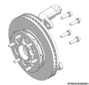
2. 2WD (High ride suspension specifications)
1) Install the knuckle cap to the knuckle.
2) Install the front hub and brake rotor to the knuckle.
3) Install the bolt to the knuckle.
Tightening torque: 85 N・m { 8.7 kgf・m / 63 lb・ft }
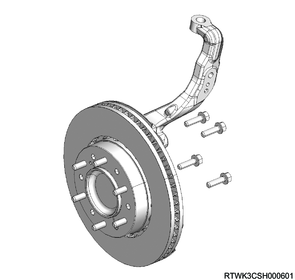
3. 4WD
1) Install the front hub and brake rotor to the knuckle.
2) Install the bolt to the knuckle.
Tightening torque: 85 N・m { 8.7 kgf・m / 63 lb・ft }
3) Install the washer and lock nut to the front hub.
Tightening torque: 127 N・m { 13.0 kgf・m / 94 lb・ft }
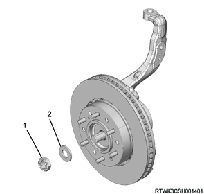
Legend
- Lock nut
- Washer
4) Install the cotter pin to the front hub.
Caution
- If the cotter pin hole position does not align, rotate the lock nut in the tightening direction to align it.
5) Install the hub cap to the front hub.
3. Brake caliper installation
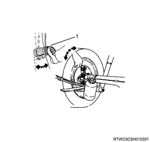
1) Referring to the diagram, apply NIGLUBE RX-2 rubber grease or equivalent to the following parts.
- Inside of the boot
- Slide pin boot mounting groove and entire circumference of the sliding section
- Entire circumference of the slide pin sliding hole on the brake support
- Entire circumference of the brake support boot groove and end surface of the brake support
- Outer circumference of the pin bushing (sliding section)
Caution
- Do not use mineral grease.
Grease application area (Boot, slide pin)
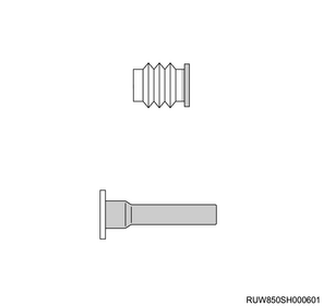
2) Install the boot to the brake support.
Note
- Install the boot securely to the brake support groove.
Caution
- Do not reuse the boot.
3) Install the slide pin to the brake support.
Note
- Install the slide pin securely to the slide pin groove.
4) Slightly pull out the slide pin to make sure that the boot is securely installed to the brake support groove.
5) Move the slide pin to spread the rubber grease over the brake support groove.
Caution
- Do not mix-up the top and bottom of the slide pin.

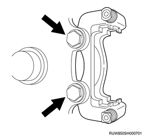
6) Install the brake support to the knuckle.
Tightening torque: 205 to 245 N・m { 20.9 to 25.0 kgf・m / 151 to 181 lb・ft }
7) Install the pad clip onto the brake support.
Caution
- Do not reuse the pad clips.
8) Install the disc brake pad and shim to the brake support.
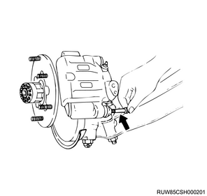
9) Install the brake caliper to the brake support.
10) Install the lock bolt to the brake caliper.
Tightening torque: 32 to 42 N・m { 3.3 to 4.3 kgf・m / 24 to 31 lb・ft }
4. Brake hose connect
1) Clean dust or foreign material on the following parts.
- Bolt
- Brake side screw
2) Install the following parts to the brake hose, and connect the brake hose to the brake caliper.
- Bolt
- Gasket
Caution
- Insert the brake hose end into the detent hole.
- Do not reuse the gasket.
Tightening torque: 29 to 39 N・m { 3.0 to 4.0 kgf・m / 21 to 29 lb・ft }
Legend
- Gasket
5. Disc wheel installation
1. Models with aluminum wheels
1) Temporarily tighten the disc wheel to the vehicle.
2) Lower vehicle.
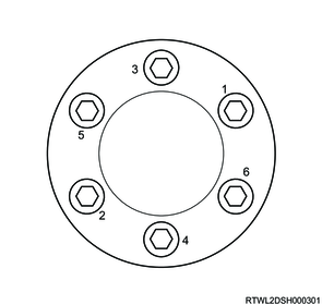
3) Final tighten the wheel nut in the order shown in the diagram.
Tightening torque: 120 N⋅m {12 kgf⋅m / 87 lb⋅ft}
Caution
- After completing installation, make sure to further tighten the wheel nuts to the specified torque after the vehicle has been driven a distance exceeding the standard value.
Standard: 50 to 100 km { 31 to 62 mile }
4) Install the wheel cap to the disc wheel.
Note
- For models with 18-inch aluminum wheels, align the wheel cap groove with the air valve before installing.
5) Check that the surfaces of the wheel cap and wheel are flat.
Note
- If the surfaces are not flat, the wheel cap may fall off.
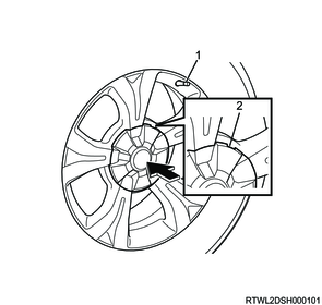
Legend
- Valve
- Wheel cap groove
2. Models with steel wheels
1) Temporarily tighten the disc wheel and wheel cap to the vehicle.
2) Lower vehicle.
3) Final tighten the wheel nut in the order shown in the diagram.
Tightening torque: 120 N⋅m {12 kgf⋅m / 87 lb⋅ft}
Caution
- After completing installation, make sure to further tighten the wheel nuts to the specified torque after the vehicle has been driven a distance exceeding the standard value.
Standard: 50 to 100 km { 31 to 62 mile }
6. Preliminary and post procedures
1) Open the engine hood.
7. Brake fluid filling
The air bleeding procedure needs cooperation of 2 persons.
1. Precautions for brake fluid refill and air bleeding procedures
Caution
- In the following cases, refill with brake fluid and bleed the air.
- The brake pipe, brake hose, etc., have been disconnected.
- Air is in the hydraulic system.
- Brake fluid has been drained.
- The brake is used when the fluid level in the brake fluid tank is extremely low.
Caution
- Securely engage the parking brake during the air bleeding procedure.
- When refilling with brake fluid and bleeding the air with the tires in contact with the ground, move the vehicle to a level area, and set chock blocks in place at the tires.
- Always fill with new brake fluid.
- Fill with brake fluid to prevent the mixing in of air bubbles.
- To prevent intrusion of dirt, etc., clean the reservoir tank before removing the cap.
- Add brake fluid up to the tank MAX level before the air bleeding procedure to prevent air from entering.
- Do not fill the brake fluid tank with brake fluid over the MAX level.
- Continue to adding brake fluid to at least half the brake fluid tank during the air bleeding procedure.
The brake fluid tank is shared with the clutch fluid tank. Because a partition inside the tank causes the fluid amounts of the brake chamber and clutch chamber to be different, check the brake fluid on the brake chamber side.
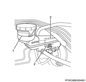
Legend
- MAX level
- MIN level
- Brake fluid chamber
Caution
- Bleed air until air has been fully discharged from the hydraulic system.
- Perform air bleeding procedures while maintaining sufficient brake fluid levels.
- Use the following brake fluid brands.
Refer to "201.General Information 14B.Vehicle Information recommended fluids, lubricants and diesel fuels".
Caution
- Do not use any brake fluid that contains petroleum components.
The rubber parts in the hydraulic brake system will expand or warp.
Caution
- Do not use any brake fluid container that contains petroleum components or that is wet with water.
If water has entered, the boiling point of the brake fluid will be lowered.
Caution
- Seal all containers to prevent them from getting dirty.
- Because the painted surface will be damaged, do not spill brake fluid on a painted surface.
- Bleed air from the brake fluid while the engine is running, and ventilate the room properly.
The vacuum brake booster may be broken if air bleeding is performed without starting the engine.
Caution
- Be sure to check the brake fluid level on the brake fluid chamber side.
The brake fluid tank is shared with the clutch fluid tank, and a partition inside the tank causes the fluid amounts of the brake chamber and clutch chamber to be different.
Caution
- For models with ABS specifications, remove the ABS slow blow fuse before performing the air bleeding procedure.
The ABS unit may be broken if air bleeding is performed without removing the ABS slow blow fuse.
2. Preparations for brake fluid refill and air bleeding procedures
Open the engine hood after pulling the parking brake lever.
1) Apply the parking brake.
2) Start the engine.
3) Remove the cap from the brake fluid tank.
4) Replenish the brake fluid tank with the brake fluid.
5) Perform the air bleeding procedure in the following order.
- Brake master cylinder (When the brake master cylinder has been removed)
- Left rear wheel cylinder
- Right rear wheel cylinder
- Left front brake caliper
- Right front brake caliper
Note
- If the brake fluid level is lowered or if air enters when the brake pipe is removed from the master cylinder, the air bleeding may be required at all 4 brakes.
- When brake pipes have been removed from any of the brakes, air bleeding must be performed for that wheel cylinder or caliper.
- If the piping is removed between the master cylinder and each brake, air bleeding of the operating brake system needs to be performed at the removed piping.
3. Air bleeding (Brake master cylinder)
1) Inspect the brake fluid level.
Note
- Refill the brake fluid as necessary.
- If the brake fluid has been filled, leave the system for at least 1 minute.
2) Disconnect the rear brake pipe from the brake master cylinder.
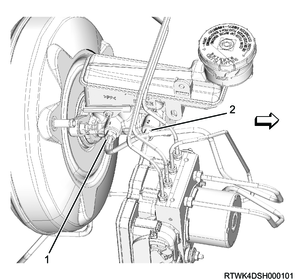
Legend
- Front brake pipe
- Rear brake pipe
3) Slowly depress the brake pedal once and hold it down.
4) Use a finger to completely plug the outlet of the master cylinder that is removed from the brake pipe, and slowly release the brake pedal.
5) Remove the finger from the outlet after the brake pedal has been completely returned.
Note
- Repeat the process mentioned above until the brake fluid comes out overflowing from the outlet.
Caution
- Be careful that the fluid level in the reservoir tank does not drop below the intermediate level indication.
6) Connect the brake pipe to the brake master cylinder.
7) Slowly depress the brake pedal once and hold it down.
8) Loosen the rear brake pipe.
9) Tighten the brake pipe again and slowly return the brake pedal.
Tightening torque: 13 to 19 N・m { 1.3 to 1.9 kgf・m / 10 to 14 lb・ft } Except ESC specifications
Tightening torque: 16 to 24 N・m { 1.6 to 2.4 kgf・m / 12 to 18 lb・ft } ESC specifications
10) Repeat the above procedure until no air is bled from the outlet when loosening the brake pipe.
11) Bleed the front brake pipe in the same way.
4. Air bleeding (Brake wheel cylinder or brake caliper)
Caution
- Bleed air 10 times or more for the front wheel, and 15 times or more for the rear wheel.
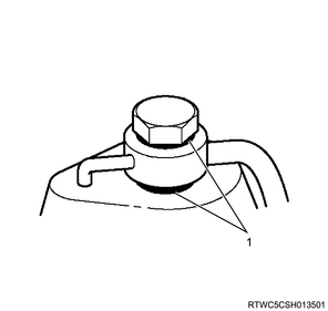
1) Apply an appropriate wrench to the bleeder.
2) Connect a clear tube to the bleeder.
3) Dip one end of the tube into a clear container filled with brake fluid.
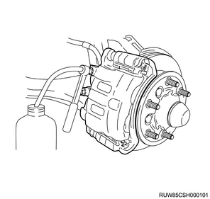
Note
- The container should be approximately 1/3 full of brake fluid.
4) Slowly depress the brake pedal 3 times with a speed of once per second and hold it down.
Legend
- Brake pedal
5) Loosen the bleeder approximately 1/2 a turn and bleed the air from the brake fluid.
6) Tighten the bleeder.
| Brake type |
Tightening torque |
| Front disc brake |
9 to 13 N・m { 0.9 to 1.3 kgf・m / 80 to 115 lb・in } |
| Rear drum brake |
6 to 8 N・m { 0.6 to 0.8 kgf・m / 53 to 71 lb・in } |
7) Release the brake pedal.
Caution
- Repeat the process mentioned above until no air bubbles are found in the discharged brake fluid.
- If brake fluid does not come out, discharge air from the master cylinder.
Air has entered the master cylinder.
5. Inspection after bleeding air
1) After air bleeding is complete, depress the brake pedal and check for any abnormal conditions.
2) Check the brake fluid level in the brake fluid tank, and fill the brake fluid tank with brake fluid as necessary.
Caution
- When filling, do not exceed the MAX level.
3) Depress the brake pedal and check for a sponge-like feeling.
Caution
- If feeling like a sponge, repeat the air bleeding process.
4) Stop the engine.
Note
- After completing the air bleeding procedure for the brake system, bleed the air from the clutch system as necessary.
5) Inspect all the brake pipes and brake hoses for the following.
- Wear
- Bending
- Damage
- Cracking
- Dent
Note
- Repair or replace if any abnormal conditions are found.
Caution
- Joints of all pipes and hoses can be easily damaged.
- Do not twist or bend the hose excessively when performing the procedure. Do not break the brake pipe when repairing or replacing the axle, suspension, etc.
- When installing the brake pipe or the brake hose, make sure to perform inspection.
- After removing the brake pipe or the brake hose, use a plug, tape, etc., to cover the opening and prevent the intrusion of foreign material.
6) Close the engine hood.
6. ABS slow blow fuse installation (ABS specifications)
1) Install the ABS slow blow fuse to the fuse box.
2) Turn ON the ignition switch and make sure the warning light turns OFF.
Caution
- Clear the DTCs that were set to the EHCU by removing fuses.