1. Component views
Transfer

Part name
- Input shaft
- Transfer case
- 2-4 switch
- Dummy plug (Models with ABS)
- Bolt
- Speedometer driven gear (Models without ABS)
- Speedometer bushing (Models without ABS)
- Speedometer stay (Models without ABS)
- Bolt
- Bolt
- Transfer actuator
- Bolt
- Stone guard
- Front companion flange
- End nut
- Neutral switch
- Detent plug
- Bolt
- Switch bracket
Tightening torque
3: 39 N・m { 4.0 kgf・m / 29 lb・ft }
5: 15 N・m { 1.5 kgf・m / 11 lb・ft }
9: 15 N・m { 1.5 kgf・m / 11 lb・ft }
10: 22 N・m { 2.2 kgf・m / 16 lb・ft }
12: 21 N・m { 2.1 kgf・m / 15 lb・ft }
15: 137 N・m { 14.0 kgf・m / 101 lb・ft }
16: 39 N・m { 4.0 kgf・m / 29 lb・ft }
17: 19 N・m { 1.9 kgf・m / 14 lb・ft }
18: 15 N・m { 1.5 kgf・m / 11 lb・ft }
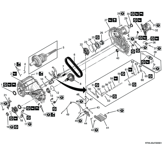
Part name
- Input shaft oil seal
- Transfer case
- Breather pipe (Transfer)
- Breather hose (Transfer)
- Main shaft assembly
- Transfer chain
- Shift drum shaft
- Front output shaft
- Shift drum
- Bushing
- Breather pipe (Actuator)
- Snap ring
- Front output shaft ball bearing
- 2-4 switch
- Detent plug, spring, and detent ball
- Front output shaft oil seal
- Neutral switch
- Front companion flange
- End nut
- Bolt
- Switch bracket
- Oil pump
- Oil pump retaining ring
- Retaining ring
- Ball bearing
- Speedometer drive gear
- Rear transfer cover
- Bolt
- Snap ring
- Rear output shaft oil seal
- Bolt
- Transfer actuator
- Shift drum oil seal
- Filler plug
- Drain plug
- Dummy plug (Models with ABS)
- Bolt
- Speedometer driven gear, speedometer bushing, and speedometer stay (Models without ABS)
- Bolt
- Needle bearing
- Stone guard
- Bolt
- Screen assembly
- Buffer plate
- Bolt
- Bolt
- Clamp
- Hose
- Breather hose (Actuator)
- H-L shift arm
- Spring pin
- H-L shift block
- Guide roller
- Inner retaining ring
- Front collar
- Shift block spring
- Rear collar
- Shift rod
- Outer snap ring
- Snap ring
- 2-4 shift rod
- 2-4 shift arm
- Shift block spring
- 2-4 shift block
- Spring pin
- Guide roller
Tightening torque
14: 39 N・m { 4.0 kgf・m / 29 lb・ft }
15: 19 N・m { 1.9 kgf・m / 14 lb・ft }
17: 39 N・m { 4.0 kgf・m / 29 lb・ft }
19: 137 N・m { 14.0 kgf・m / 101 lb・ft }
20: 15 N・m { 1.5 kgf・m / 11 lb・ft }
28: 22 N・m { 2.2 kgf・m / 16 lb・ft }
31: 22 N・m { 2.2 kgf・m / 16 lb・ft }
34: 39 N・m { 4.0 kgf・m / 29 lb・ft }
35: 39 N・m { 4.0 kgf・m / 29 lb・ft }
37: 15 N・m { 1.5 kgf・m / 11 lb・ft }
39: 15 N・m { 1.5 kgf・m / 11 lb・ft }
42: 21 N・m { 2.1 kgf・m / 15 lb・ft }
45: 15 N・m { 1.5 kgf・m / 11 lb・ft }
46: 15 N・m { 1.5 kgf・m / 11 lb・ft }
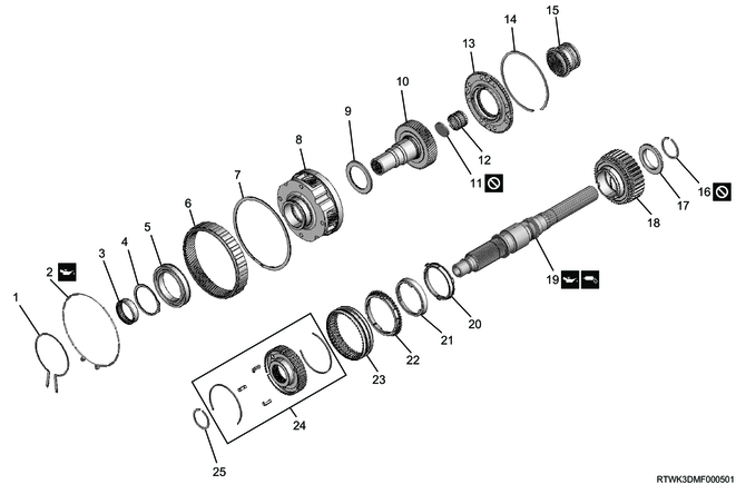
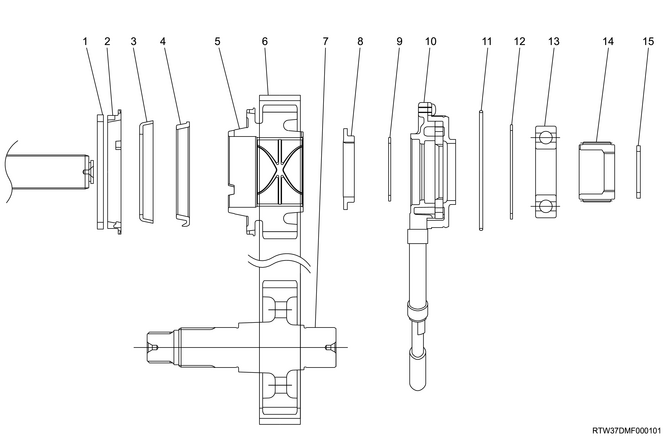
Part name
- Outer retaining ring
- Damper ring
- Needle bearing
- Carrier snap ring
- Input shaft ball bearing
- Internal gear
- Retaining ring (Spiral type)
- Carrier
- Thrust needle bearing
- Sun gear input shaft
- Seal cap
- Sun gear needle bearing
- Planetary dog teeth
- Dog teeth snap ring
- H-L sleeve
- Sprocket snap ring
- Sprocket thrust washer
- Drive sprocket
- Main shaft
- Inside ring
- Outside ring
- Block ring
- 2-4 sleeve
- Synchronizer key spring, synchronizer key, and 2-4 hub
- Hub snap ring
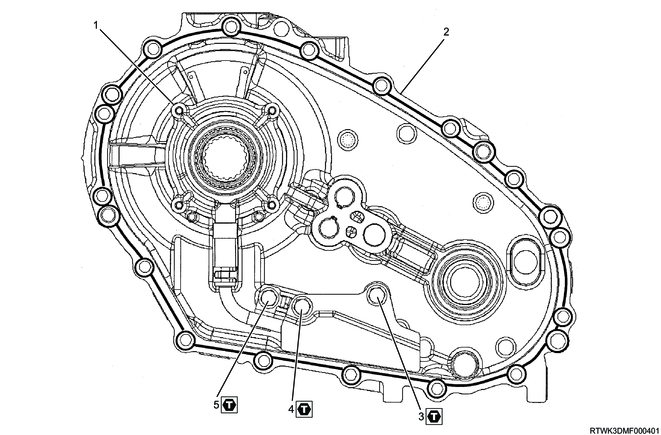
Part name
- Oil pump
- Rear transfer cover
- Bolt
- Bolt
- Bolt
Tightening torque
3: 15 N・m { 1.5 kgf・m / 11 lb・ft }
4: 15 N・m { 1.5 kgf・m / 11 lb・ft }
5: 15 N・m { 1.5 kgf・m / 11 lb・ft }
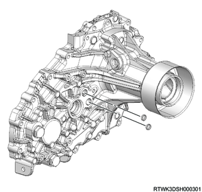
2. Stone guard removal
1) Remove the stone guard from the transfer case.
3. Speedometer driven gear removal
1. Models with ABS
1) Remove the dummy plug from the rear transfer cover.
2. Models without ABS
1) Remove the following parts from the rear transfer cover.
- Speedometer stay
- Speedometer bushing
- Speedometer driven gear
4. Transfer disassembly
1) Remove the breather hose from between the transfer case and the transfer actuator.
2) Remove the following parts from the transfer case.
- Breather pipe (Transfer)
- Breather pipe (Actuator)
- Breather hose (Transfer and actuator)
3) Remove the transfer actuator from the rear transfer cover.
4) Remove the shift drum oil seal from the rear transfer cover.
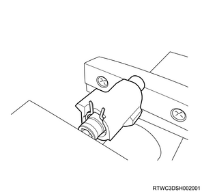
5) Remove the switch bracket from the transfer case.
6) Remove the 2-4 switch of the gray harness cover from the transfer case.
7) Remove the neutral switch of the brown harness cover from the transfer case.
8) Remove the following parts from the transfer case.
- Detent plug (2 pcs.)
- Detent spring (2 pcs.)
- Detent ball (2 pcs.)
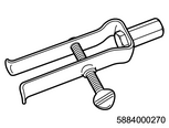
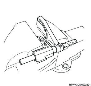
9) Remove the front companion flange end nut from the output shaft using the special tool.
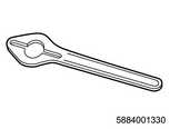
SST: 5-8840-0133-0(J-8614-11) - flange holder
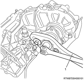
Legend
- 5-8840-0133-0 (J-8614-11)
10) Remove the front companion flange from the output shaft.
11) Remove the O-ring from the front output shaft.
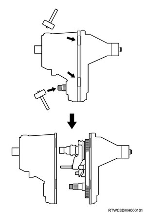
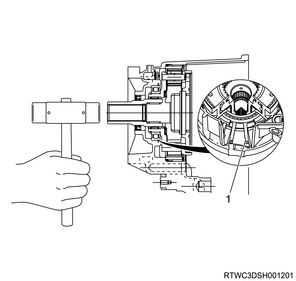
12) Remove the rear transfer cover from the transfer case.
Note
- With a plastic hammer, tap the front output shaft head and the section around the rear cover bolt hole, and remove the rear cover.
13) Remove the bushing from the transfer case.
14) Remove the H-L sleeve from the output shaft.
15) Remove the H-L shift assembly from the rear transfer cover.
16) Remove the following parts from the output shaft.
- 2-4 sleeve
- Synchronizer key
- Front synchronizer spring
Note
- Do not remove the rear spring.
17) Remove the 2-4 shift assembly from the rear transfer cover.
18) Remove the shift drum and shift drum shaft from the rear transfer cover.
19) Remove the sun gear needle bearing from the main shaft.

Legend
- Sun gear needle bearing
- H-L sleeve
- 2-4 sleeve, synchronizer key, and front synchronizer spring
- 2-4 shift assembly
- Shift drum shaft
- H-L shift assembly
- Shift drum
20) Remove the mounting bolts for securing the oil pump strainer from the rear transfer cover.
21) Compress the retaining ring behind the chain.
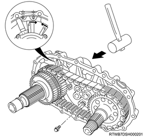
22) Remove the main shaft, transfer chain, and front output shaft assembly as a set from the transfer case.
Note
- Tap the rear end of the main shaft with a plastic hammer, and remove.
Caution
- Be careful not to damage the oil pump strainer.
23) Remove the transfer chain and the front output shaft from the main shaft.
24) Remove the main shaft snap ring from the main shaft.
25) Remove the following parts from the main shaft.
- Speedometer drive gear
- Ball bearing
- Retaining ring
- Oil pump
26) Remove the sprocket snap ring from the main shaft.
27) Remove the following parts from the main shaft.
- Sprocket thrust washer
- Drive sprocket
- Inside ring
- Outside ring
- Block ring
- Rear synchronizer spring
Legend
- Rear synchronizer spring
- Block ring
- Outside ring
- Inside ring
- Drive sprocket
- Transfer chain
- Front output shaft
- Sprocket thrust washer
- Sprocket snap ring
- Oil pump
- Oil pump retaining ring
- Retaining ring
- Ball bearing
- Speedometer drive gear
- Main shaft snap ring
28) Remove the snap ring from the main shaft.
29) Remove the 2-4 hub from the main shaft using the press.
5. Input shaft removal
1) Lightly tap the sun gear input shaft end, and expand the retaining ring edge.
Legend
- Retaining ring
2) Remove the carrier and gear assembly from the sun gear input shaft.
3) Remove the dog teeth snap ring from the carrier and gear assembly.
4) Remove the planetary dog teeth, sun gear input shaft, and thrust needle bearing as a set.
Legend
- Outer retaining ring
- Carrier and gear assembly
- Thrust needle bearing
- Seal cap
- Sun gear input shaft
- Planetary dog teeth
- Dog teeth snap ring
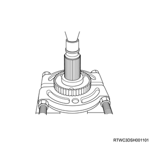
5) Lightly tap the seal cap with a tool such as a rod to remove it from the sun gear input shaft.
Caution
- Do not reuse the seal cap.
6) Remove the carrier snap ring from the carrier.

Legend
- Carrier snap ring
7) Remove the input shaft ball bearing from the carrier using a press.
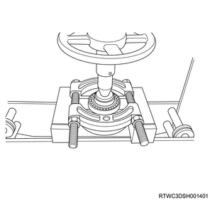
8) Remove the needle bearing from the center of the carrier and gear assembly using the special tool.

SST: 5-8840-0084-0 - sliding hammer
SST: 5-8840-0027-0 - remover
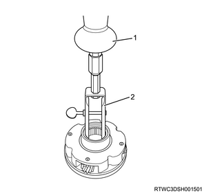
Legend
- 5-8840-0084-0
- 5-8840-0027-0
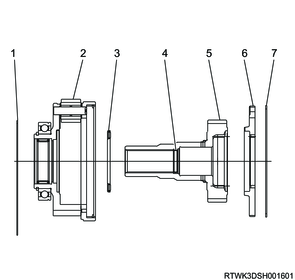
6. Transfer case disassembly
1) Remove the spiral-type retaining ring, internal gear, and damper ring as a set.
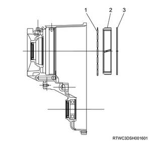
Legend
- Damper ring
- Internal gear
- Retaining ring
2) Remove the snap ring from the transfer case.
3) Remove the front output shaft ball bearing from the transfer case using a press.
4) Remove the oil pump wire snap ring from the rear transfer cover.
5) Remove the needle bearing from the rear transfer cover using the special tool.
SST: 5-8840-0084-0 - sliding hammer

SST: 5-8840-2788-0 - bearing remover
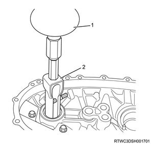
Legend
- 5-8840-0084-0
- 5-8840-2788-0
6) Remove the shift rod hole plug from the rear transfer cover.
7) Remove the following parts from the oil pump.
- Clamp (Screen side)
- Screen
- Clamp (Hose side)
- Hose
Caution
- The oil pump maintains and protects the oil pump functions, therefore do not disassemble it regardless of the conditions.
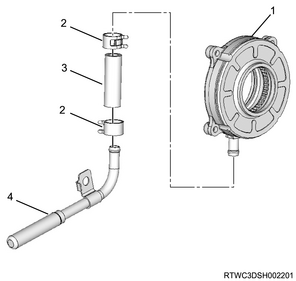
Legend
- Oil pump
- Clamp
- Hose
- Screen
7. Shift arm removal
1. Disassembly of the H-L shift assembly
1) Remove the guide roller from the shift block.
2) Compress the H-L shift spring using a vise.
3) Remove the outer snap ring from the shift rod.
4) Compress the spring inside the shift block using the socket and the vise.
5) Remove the inner retaining ring from the shift rod.
6) Remove the rear collar from the shift rod.
7) Remove the shift block spring from the shift rod.
8) Remove the front collar from the shift rod.
9) Remove the shift block from the shift rod.
10) Remove the spring pin from the shift arm, and remove the shift arm from the shift rod.
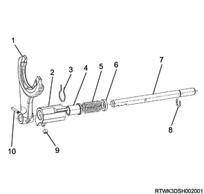
Legend
- Shift arm
- Shift block
- Inner retaining ring
- Front collar
- Shift block spring
- Rear collar
- Shift rod
- Outer snap ring
- Guide roller
- Spring pin
2. Disassembly of H-L shift arm (Only models with pads)
1) Remove the pads from the shift arm.
Caution
- Because the pin section at the center of the pad is press-fitted into the shift arm, the pad may be damaged if it is removed by holding the positioning pin side.
- Remove the pads carefully while pulling out the press-fit pin by applying force near the press-fit pin.
- If the pads are bent during the removal, do not reuse them.
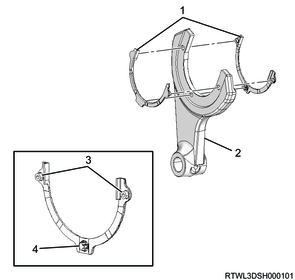
Legend
- Pad
- Shift arm
- Positioning pin
- Press-fit pin
3. Disassembly of 2-4 shift assembly
1) Remove the guide roller from the shift block.
2) Compress the spring, and remove the snap ring from the shift rod.
3) Remove the shift arm and spring from the shift rod.
4) Remove the spring pin from the shift block.
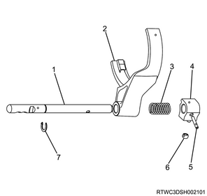
Legend
- Shift rod
- Shift arm
- Spring
- Shift block
- Spring pin
- Guide roller
- Snap ring