1. Transfer inspection
Caution
- If any wear, damage, or other abnormalities are found, repair or replace the defective parts.
- Clean all parts with clean cleaning fluid, and check if old oil, metal particles, fouling, or foreign materials are removed completely.
- Blow compressed air to each oil feed port and channel inside each case half, and remove foreign materials or remaining cleaning fluid.
1. Chain inspection
1) Inspect the surface that makes contact with the sprocket for excessive wear or damage.
Note
- Replace if wear or damage is excessive.
- If there are any signs of interfering of the chain with the transfer cover inner wall, replace the chain.
- If the chain and the sprocket do not engage due to chain stretch, replace the chain.
2. Drive sprocket inspection
1) Inspect the sprocket tooth surfaces for excessive wear or damage.
2) Inspect the gear spline section for the following conditions.
- Burrs
- Chipping
- Signs of wear or damage
Note
- Repair small cracks or scratches by using an oil stone.
- If excessive wear or damage is found, replace the defective parts.
- If excessive wear or damage is found on the sprocket inside sliding surface, replace the defective parts.
3. Gear inspection
1) Inspect the gear tooth surfaces for excessive wear or damage.
2) Inspect the gear spline section for the following conditions.
- Burrs
- Chipping
- Signs of wear or damage
Note
- Repair small cracks or scratches by using an oil stone.
- If excessive wear or damage is found, replace the defective parts.
4. Bearing inspection
1) Completely clean the bearing with a cleaning fluid, and blow compressed air.
2) Apply diesel oil to the bearing, and inspect the condition of the bearing while slowly rotating the race.
Note
- Inspect the status of all needle bearings and ball bearings.
Caution
- Slowly turn the bearing by hand; do not rotate it quickly.
- If the bearing rotates quickly, it may damage the roller.
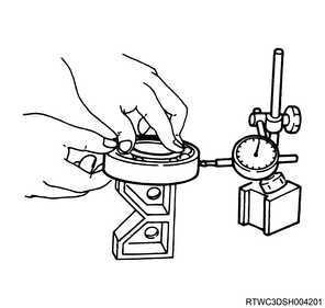
3) Inspect the ball bearing for play using a dial indicator.
Note
- If the measured value exceeds the limit, replace the ball bearing.
Limit: 0.2 mm { 0.008 in }
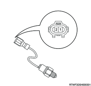
5. Switch inspection
1) Inspect the 2-4 and neutral switches for continuity.
Note
- Replace the 2-4 switch and the neutral switch if a malfunction is found.
| Switch stroke |
2-4 switch signal |
Neutral switch signal |
| Terminal 1-2 |
Terminal 1-2 |
|
| 1 |
Open |
Close |
| 2 |
Close |
Open |
Legend
- Switch stroke
- Switch stroke
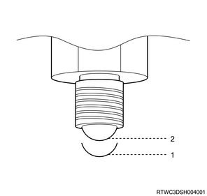
6. Oil pump inspection
1) Remove the foreign material from the strainer.
Note
- Replace the strainer if damaged.
- If the shaft insertion section is excessively worn or damaged, replace the oil pump.
7. Transfer synchronizer assembly inspection
1) Clean the synchronizer components with clean cleaning fluid and dry.
Caution
- The synchronizer hub and the sliding sleeve have been selected for the optimal combination, and therefore, do not change the original combination.
2) Inspect the transfer synchronizer components for the following.
- Worn gear
- Damage
- Chipping
- Burrs or cracks
Note
- Replace the key or spring if wear, cracking, or deformation is found.
- If wear, chipping, or burrs cannot be repaired using a grindstone or crocus cloth, replace the component.
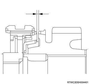
8. Clutch hub inspection
1) Set a dial gauge to the clutch hub.
2) Move the clutch hub right and left to read the runout width of the gauge needle.
Note
- If the measured value exceeds the limit, replace the clutch hub.
Standard: 0.0 to 0.1 mm { 0.000 to 0.004 in }
Limit: 0.2 mm { 0.008 in }

3) Use a feeler gauge to measure the clearance between the clutch hub and the insert.
Note
- Replace the clutch hub and the insert if the measured value exceeds the limit.
Standard: 0.01 to 0.19 mm { 0.0004 to 0.0075 in }
Limit: 0.3 mm { 0.012 in }
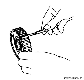
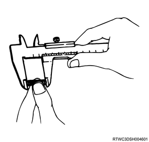
9. Block ring inspection
1) Inspect the block ring and its clearance.
2) Measure the clearance between the block ring and the insert by using a vernier caliper.
Note
- Replace the block ring and the insert if the measured value exceeds the limit.
Standard: 3.86 to 4.14 mm { 0.152 to 0.163 in }
Limit: 4.9 mm { 0.193 in }

10. Synchronizer cone inspection
1) Inspect the 2WD-4WD synchronizer and 3 cones.
2) Measure the clearance between the block ring and the dog teeth using a feeler gauge.
Note
- Replace the 2WD-4WD synchronizer assembly if the measured value exceeds the limit.
Standard: 1.5 mm { 0.059 in }
Limit: 0.8 mm { 0.031 in }
11. Detent spring inspection
1) Inspect the detent spring for the following.
- Warped
- Crack
- Wear
Note
- Replace if a malfunction is found.
2) Measure the free length of the detent spring using a vernier caliper.
Note
- If the measured value is smaller than the limit, replace the detent spring.
Standard: 23.4 mm { 0.921 in }
Limit: 22.8 mm { 0.898 in }
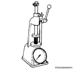
3) Measure the tension of the detent spring using a spring tester.
Note
- If the measured value is smaller than the standard value, replace the detent spring.
Standard: 18.7 mm { 0.736 in } Spring compression width at tension measurement
Standard: 68.6 to 88.2 N { 7.0 to 9.0 kg / 15.4 to 19.8 lb }
12. Shift arm inspection
1) Inspect the shift arm for the following.
- Warped
- Wear
- Scratches
2) Measure the thickness of the shift arm using a micrometer.
Note
- If the measured value is smaller than the limit, replace the shift arm.
- For models with pads, measure the thickness between the press-fit sections.
| Standard value |
7.45 to 7.98 mm { 0.293 to 0.314 in } Thickness between press-fit pin sections |
| Limit |
7.0 mm { 0.276 in } Thickness between press-fit pin sections |
| Standard value |
7.60 to 7.85 mm { 0.299 to 0.309 in } |
| Limit |
7.0 mm { 0.276 in } |
| Standard value |
9.60 to 9.85 mm { 0.378 to 0.388 in } |
| Limit |
9.0 mm { 0.354 in } |