1. Maintenance precautions of tire pressure monitoring system
1. Tire air pressure sensor handling precautions
The tire air pressure sensor is an integrated structure with the air valve and installed to each tire. (Total 5 tires: 4 tires installed on the vehicle and 1 spare tire)
Take sufficient care when handling the tire air pressure sensor.
- Do not remove the tire air pressure sensor unnecessarily during maintenance work.
- When replacing tires, do not subject the tire air pressure sensor unit to strong impact.
- Do not change the tire air pressure sensor installation position.
- Install the tire air pressure sensor according to the installation marks.
2. Battery life of tire air pressure sensor
A battery is built into the tire air pressure sensor. The battery life is approximately 10 years for normal use.
Note
- Since the battery cannot be replaced separately, the tire air pressure sensor unit needs to be replaced if the battery is drained.
3. Tire air pressure monitoring system precautions
If any of the following are applicable, the tire air pressure monitoring system does not operate.
- A tire that is not equipped with a tire air pressure sensor is used.
- The tire air pressure sensor ID is not registered in the wireless access module.
- The TPMS warning light illuminates after flashing for 63 seconds. (DTC is set.)
If any of the following are applicable, the tire air pressure monitoring system may not operate properly.
- Non-genuine wheel is used.
- A tire other than equipped at the time of factory shipment has been used as replacement.
- The tire chain is installed.
- Adhesion of large amounts of mud, snow, ice, etc., to the vehicle (especially around the tire)
- The film to block radio waves is attached on the window.
- The tire air pressure is extremely high as compared to the specified air pressure.
- Air pressure has decreased abruptly due to tire blowout.
- An aftermarket puncture sealant has been used.
- Communication devices such as mobile phones, wireless devices, laptop computers, etc., are placed near the installation position of the wireless access module.
- Near places with strong electromagnetic interference (television tower, power plant, radio station, etc.)
Note
- If tire-related parts (tires, wheels, wheel nuts, etc.) have been replaced, the tire air pressure monitoring system may not operate properly.
4. Safety precautions
The exhaust gas is highly poisonous and can lead to fainting and/or death. When performing an inspection with the engine ON in a closed location such as a garage, make sure there is adequate ventilation in the area to ensure no exhaust gas is breathed in. Before inspecting with a scan tool, firmly engage the parking brake. Also, use chock blocks to stabilize the vehicle.
5. Using circuit test tools
Unless instructed in the diagnostic procedure, do not use a test lamp. When a probe connector is required in a diagnostic procedure, use connector test adapter kit (5-8840-2835-0).
6. Commercial electronic equipment
Aftermarket electronic equipment refers to commercially available electronic equipment installed to the vehicle after it has been shipped from the factory. Be careful, as such accessories are not taken into particular consideration at the vehicle design stage.
Aftermarket electronic equipment may cause malfunctions in the electronic control system, even if the equipment is properly installed. Aftermarket electronic equipment includes devices not connected to the electronic control system of the vehicle, such as mobile phones or radios. Therefore, when diagnosing problems in the electronic control system, first check whether such aftermarket electronic equipment is installed. Remove it from the vehicle if installed. If the problem has not been resolved after removing the equipment, perform the diagnosis using the regular procedure.
Caution
- Make sure that both the power supply and ground of aftermarket electronic equipment are connected to a circuit that is not related to the circuits of the electronic control system.
7. Damage caused by static electricity
Because the electronic components used in the electronic control system are designed to operate at extremely low voltages, they can be easily damaged by static electricity, and some types of electronic components can be damaged by static electricity of 100 V or less, which cannot be felt by a person. (A voltage of 4,000 V is required for a person to be able to detect static electricity.)
There are various ways a person can build up an electrostatic charge. The most common way to build up an electrostatic charge is through friction or induction. An example of when a person builds an electrostatic charge by friction is when they slide across the seat of the vehicle. A person wearing insulated shoes can build an electrostatic charge by induction if they momentarily touch the ground while standing near a highly charged object. A charge of the same polarity flows out, and with a highly opposing polarity, that person becomes charged. Because static electricity can be damaging, be extremely careful when handling or testing electronic components.
Caution
- To prevent damage caused by static electricity, do not touch the connector pins of the wireless access module or the electronic components soldered onto the circuit board of the wireless access module.
- To prevent damage caused by static electricity, do not open the packaging of a replacement part until the preparations for installation of the part are completed.
- To prevent damage caused by static electricity, connect the package to a properly working vehicle ground before removing the part from the package.
- To prevent damage caused by static electricity, touch a properly working ground before installing the part in such cases as when handling the part while sliding across a seat, when sitting down from a standing position, or while walking a certain distance.
8. Tools to be used
When measuring the voltage and resistance, make sure to correctly use the tools, such as the scan tool, connector test adapter kit (5-8840-2835-0), digital multimeter [DMM] (5-8840-0285-3), and trigger tool.
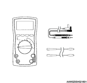
9. Digital multimeter (DMM)
Use the specified [DMM] (5-8840-0285-3) for diagnosing or repairing the wireless access module. Use of the other DMMs for diagnosing or repairing the wireless access module is not allowed.
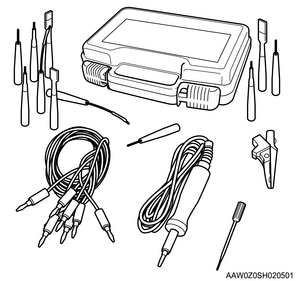
10. Connector test adapter kit
Use the connector test adapter kit (5-8840-2835-0) when the diagnostic procedure requires inspection or detailed checking using a terminal. Use the appropriate adapter to prevent the terminal from being damaged.
11. Trigger tool
The trigger tool is used to activate the tire air pressure sensor. The trigger tool is necessary when performing the following operations.
- When performing wireless access module programming
- During diagnosis, when identifying the tire air pressure sensor installed in each tire
- When observing the tire air pressure sensor data on the scan tool while the vehicle is stopped and not running
12. Trigger tool usage
1) Face the trigger tool toward the tire air pressure sensor installed to each tire.
2) Press the trigger tool activation button (left side button).
3) After the tire air pressure sensor is activated, press the trigger tool activation stop button (right side button).
Note
- If 2 or more tire air pressure sensors are activated at the same time when using a trigger tool, perform again after removing the spare tire from the vehicle.