1. Cylinder head installation
1) Clean the upper surface of the cylinder block and lower surface of the cylinder head using a scraper.
Caution
- Do this carefully so as to not damage the upper surface of the cylinder block or lower surface of the cylinder head.
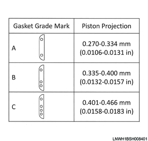
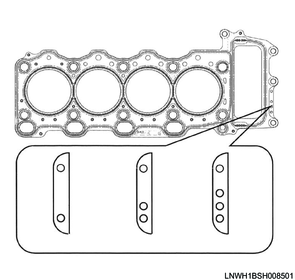
2) Prepare a cylinder head gasket with the same grade as the removed gasket.
Caution
- Do not reuse the cylinder head gasket.
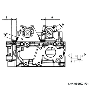
3) Apply ThreeBond 1207B or equivalent to the positions on the cylinder block shown in the diagram.
Caution
- After applying the liquid gasket, install the cylinder head within 5 minutes.
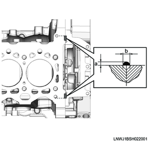
Standard value
a: 2.0 to 3.0 mm { 0.079 to 0.118 in } Bead height
b: 3.0 to 4.0 mm { 0.118 to 0.157 in } Bead width
4) Place the cylinder head gasket on the cylinder block.
Caution
- Do not reuse the cylinder head gasket.
5) Align the dowel positions, and place the cylinder head on the cylinder block.
Caution
- Do not damage the cylinder head gasket.
6) Apply engine oil to the following locations.
- Cylinder head mounting bolt threaded portion
- Cylinder head mounting bolt seating surface
- Washer
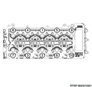
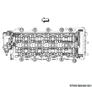
7) Tighten the cylinder head bolts to the cylinder head using the special tool and a torque wrench in the order shown in the diagram.
Caution
- Do not reuse the cylinder head bolts.

SST: 5-8840-0266-0 - angle gauge
Tightening torque: 115 N・m { 11.7 kgf・m / 85 lb・ft } 1st time
Tightening torque: 115 N・m { 11.7 kgf・m / 85 lb・ft } 2nd time
Note
- Retighten to the same torque to prevent variations in the tightening torque.
Tightening Angle : 90 to 120 ° 3rd time
Tightening Angle : 90 to 120 ° 4th time
8) Install the bolts to the flywheel housing in the order shown in the diagram.
Tightening torque: 25 N・m { 2.5 kgf・m / 18 lb・ft }
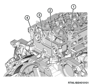
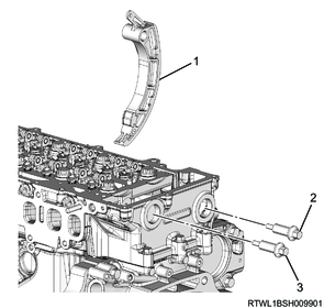
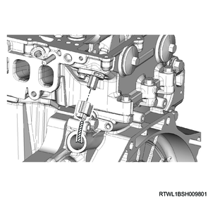
9) Install the following parts to the cylinder head.
- Timing chain tension lever
- Timing chain guide bolt
- Timing chain lever pivot
Tightening torque: 25 N・m { 2.5 kgf・m / 18 lb・ft }
Legend
- Timing chain tension lever
- Timing chain guide bolt
- Timing chain lever pivot
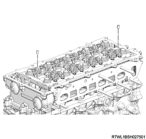
10) Apply LOCTITE 262 to the threaded portion of the plug.
11) Install the plug to the cylinder head.
Tightening torque: 25 N・m { 2.5 kgf・m / 18 lb・ft }
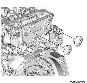
12) Connect the connector to the CMP sensor.
2. Camshaft carrier installation
1) Install the dowel pin to the cylinder head.
Note
- Insert until full contact is made.
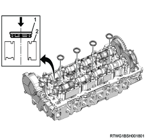
2) Check that the inlet camshaft and the exhaust camshaft notches are aligned with the camshaft cap alignment marks.
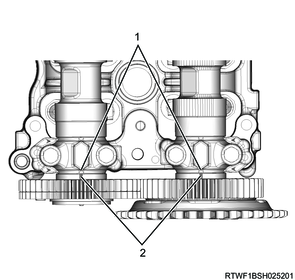
Legend
- Alignment mark
- Notch
3) Confirm that the 4 gaskets are installed to the lower surface of the camshaft carrier.
4) Referring to the diagram, apply ThreeBond 1207B to the cylinder head.
Caution
- Within 5 minutes of applying the liquid gasket, install the camshaft carrier.
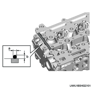
Standard value
a: 2.0 to 3.0 mm { 0.079 to 0.118 in } Bead width
b: 2.0 to 3.0 mm { 0.079 to 0.118 in } Bead height
5) Apply engine oil to the threaded portions and seating surfaces of the bolts.
6) Temporarily tighten the camshaft carrier to the cylinder head in the order shown in the diagram.
Note
- Check the rocker arm for position misalignment before and after installation.
7) Check that the camshaft carrier has been seated on the cylinder head.
8) Final tighten the camshaft carrier to the cylinder head in the order shown in the diagram.
Tightening torque: 7.0 N・m { 0.7 kgf・m / 62 lb・in }
9) Connect the vacuum hose to the vacuum pump.
10) Align the paint markings and install the timing chain to the camshaft sprocket.
Note
- Align to the marked position before removal.
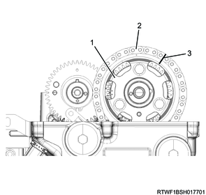
Legend
- Camshaft sprocket
- Timing chain
- Paint marking
11) Install the timing chain tensioner and gasket to the flywheel housing.
Caution
- Do not reuse the gasket.
Tightening torque: 70 N・m { 7.1 kgf・m / 52 lb・ft }
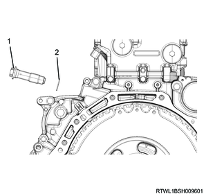
Legend
- Timing chain tensioner
- Gasket
12) Install the cam angle sensor rotor to the inlet camshaft.
Note
- Install by aligning with the positioning pin.
- Referring to the diagram, secure the section indicated by the arrow.
Tightening torque: 25 N・m { 2.5 kgf・m / 18 lb・ft }
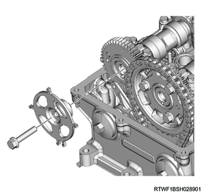
Fixing position

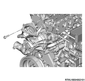
3. Thermostat housing installation
1) Apply soapy water to the O-ring.
2) Install the thermostat housing to the cylinder head and front cover.
Tightening torque: 25 N・m { 2.5 kgf・m / 18 lb・ft }
3) Connect the connector to the engine coolant temperature sensor.
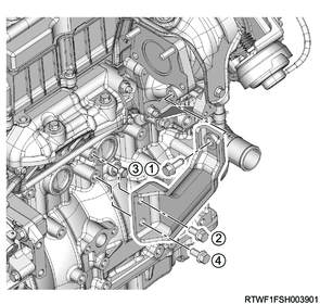
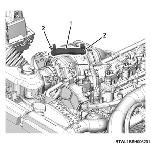
4. Turbocharger control solenoid valve installation
1) Install the bracket to the cylinder head.
Tightening torque: 25 N・m { 2.5 kgf・m / 18 lb・ft }
2) Install the turbocharger control solenoid valve to the bracket.
Tightening torque: 10 N・m { 1.0 kgf・m / 7 lb・ft }

3) Install the connector to the turbocharger control solenoid valve.
4) Connect the vacuum hose to the turbocharger control solenoid valve.
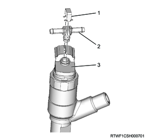
5. Common rail (fuel rail) installation
1) Install the common rail (fuel rail) to the cylinder head.
Tightening torque: 25 N・m { 2.5 kgf・m / 18 lb・ft }
Caution
- Do not hold the FRP sensor.
- Take care not to damage the connector section of the FRP sensor.
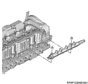
2) Install the connector to the FRP sensor.
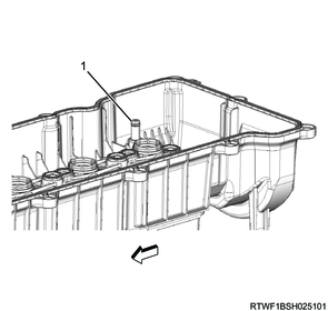
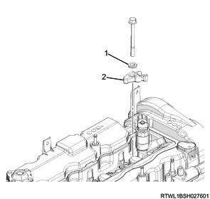
3) Install the bracket to the cylinder head.
Note
- Install so that the detent makes contact with the common rail (fuel rail).
Tightening torque: 25 N・m { 2.5 kgf・m / 18 lb・ft }

Legend
- Detent
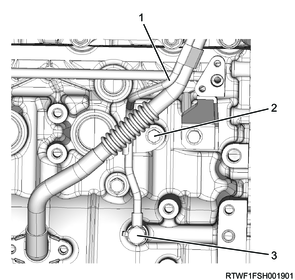
6. Fuel feed pipe installation
1) Install the fuel feed pipe to the fuel supply pump and common rail (fuel rail).
Caution
- Do not reuse the fuel feed pipe.
Tightening torque: 35 N・m { 3.6 kgf・m / 26 lb・ft }
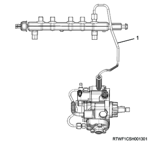
Legend
- Fuel feed pipe
2) Install the clip to the fuel feed pipe.
Tightening torque: 10.0 N・m { 1.0 kgf・m / 89 lb・in }
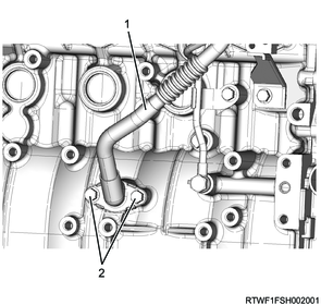
7. Fuel leak-off pipe installation
1) Install the fuel leak-off pipe to the common rail (fuel rail) and flywheel housing.
Tightening torque: 20.2 N・m { 2.1 kgf・m / 15 lb・ft } Common rail (fuel rail) side
Tightening torque: 25 N・m { 2.5 kgf・m / 18 lb・ft } Flywheel housing side

Legend
- Fuel leak-off pipe
2) Connect the fuel leak-off hose to the fuel leak-off pipe.
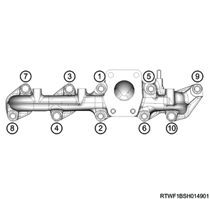
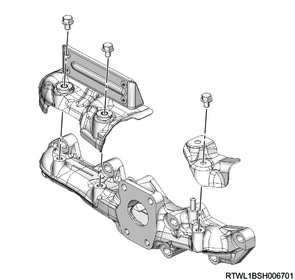
8. Exhaust manifold installation
1) Install the gasket to the cylinder head.
Note
- Face the protruding section of the gasket toward the engine front side.

Legend
- Protrusion
Caution
- Do not reuse the gasket.
2) Referring to the diagram, temporarily tighten the exhaust manifold to the cylinder head.
Tightening torque: 30 N・m { 3.1 kgf・m / 22 lb・ft }
Washer installation direction
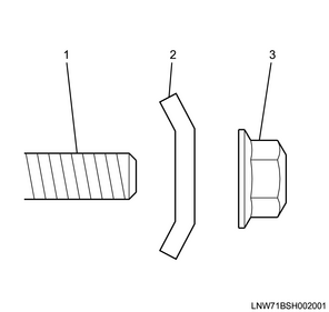
Legend
- Stud bolt
- Washer
- Nut
Spacer and washer installation direction
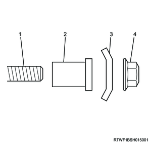
Legend
- Stud bolt
- Spacer
- Washer
- Nut
3) Securely tighten the exhaust manifold to the cylinder head.
Tightening torque: 52 N・m { 5.3 kgf・m / 38 lb・ft } 1st time
Tightening torque: 52 N・m { 5.3 kgf・m / 38 lb・ft } 2nd time
Note
- Retighten to the same torque to prevent variations in the tightening torque.
Caution
- Do not over-tighten since it will expand or contract due to the heat of the manifold.
4) Install the heat protector to the exhaust manifold.
Tightening torque: 25 N・m { 2.5 kgf・m / 18 lb・ft }
9. Turbocharger installation
1) Install the water feed and return pipe, as well as the gasket to the turbocharger.
Caution
- Do not reuse the gasket.
Tightening torque: 10.0 N・m { 1.0 kgf・m / 89 lb・in }
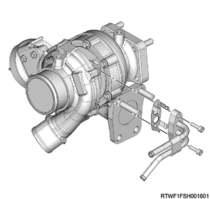
2) Feed 1 cc (approximately 20 drops) of engine oil into the oil feed port.
3) Install the turbocharger and gasket to the exhaust manifold.
Caution
- Do not reuse the gasket.
Tightening torque: 52 N・m { 5.3 kgf・m / 38 lb・ft }
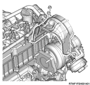
10. Turbocharger heat protector installation
1) Install the turbocharger heat protector to the turbocharger.
Tightening torque: 25 N・m { 2.5 kgf・m / 18 lb・ft }
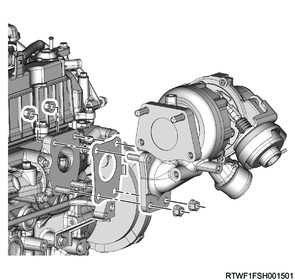
11. Turbocharger bracket installation
1) Temporarily tighten the turbocharger bracket to the turbocharger and cylinder block in the order shown in the diagram.
2) Final tighten the turbocharger bracket to the turbocharger and cylinder block in the order shown in the diagram.
Tightening torque: 52 N・m { 5.3 kgf・m / 38 lb・ft }
12. Turbocharger oil pipe installation
1) Install the turbocharger oil pipe and gasket to the turbocharger.
Caution
- Do not reuse the gasket.
Tightening torque: 10.0 N・m { 1.0 kgf・m / 89 lb・in }
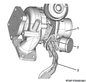
Legend
- Turbocharger
- Gasket
- Turbocharger oil pipe
2) Install the turbocharger oil pipe (feed side) to the cylinder block.
Caution
- Do not reuse the gasket.
Tightening torque: 22.5 N・m { 2.3 kgf・m / 17 lb・ft } Eyebolt
Tightening torque: 25 N・m { 2.5 kgf・m / 18 lb・ft } Bolt
Legend
- Turbocharger oil pipe (feed side)
- Bolt
- Eyebolt
3) Install the turbocharger oil pipe (return side) and gasket to the cylinder block.
Caution
- Do not reuse the gasket.
Tightening torque: 25 N・m { 2.5 kgf・m / 18 lb・ft }
Legend
- Turbocharger oil pipe (return side)
- Bolt
13. Turbocharger water hose connect
1) Connect the turbocharger water return hose to the water feed pipe and return pipe.
2) Connect the turbocharger water feed hose to the water feed pipe and return pipe.
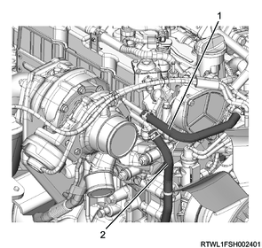
Legend
- Turbocharger water feed hose
- Turbocharger water return hose
14. Catalytic converter installation
15. Vacuum hose installation
1) Install the vacuum hose to the turbocharger and vacuum pipe.
2) Connect the vacuum hose to the turbocharger control solenoid valve.
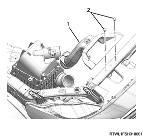
16. Air cleaner installation
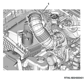
1) Install the air cleaner to the vehicle.
Tightening torque: 20 N・m { 2.0 kgf・m / 15 lb・ft }
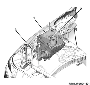
Legend
- Air cleaner
- MAF and IAT sensor
- Barometric pressure sensor
2) Connect the connector to the barometric pressure sensor.
3) Connect the connector to the MAF and IAT sensor.
17. Cylinder head cover installation
1) Install the oil seal to the cylinder head cover.
2) Install the gasket to the camshaft carrier.
Note
- Face the protruding section of the gasket toward the camshaft carrier side, and install.
Caution
- Do not reuse the gasket.
Legend
- Gasket
- Camshaft carrier
3) Apply engine oil to the cylinder head cover O-ring.
Caution
- Do not reuse the O-ring.
Legend
- O-ring
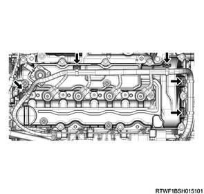
4) Referring to the diagram, apply ThreeBond 1207B to the cylinder head mating surface.
Caution
- Install the cylinder head cover within 5 minutes of applying liquid gasket.
- Remove any dirt or dust from the oil seal section on the injector connector side.
Standard value
b: 4.0 to 5.0 mm { 0.157 to 0.197 in } Bead width
c: 2.0 to 3.0 mm { 0.079 to 0.118 in } Bead height
Dimensions
a: 5.0 mm { 0.197 in }
5) Temporarily tighten the cylinder head cover to the cylinder head in the order shown in the diagram.
Caution
- Do not reuse the gasket.
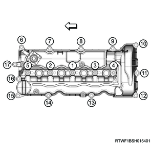
6) Final tighten the cylinder head cover to the cylinder head in the order shown in the diagram.
Tightening torque: 10.0 N・m { 1.0 kgf・m / 89 lb・in }
7) Connect the harness clip to the cylinder head cover.
8) Connect the blow-by hose to the cylinder head cover.
18. Air duct installation
1) Align the air duct with the air cleaner and turbocharger.
Legend
- Air duct
2) Referring to the diagram, align the alignment mark positions and connect the air duct to the turbocharger.
Tightening torque: 4.0 N・m { 0.4 kgf・m / 35 lb・in }
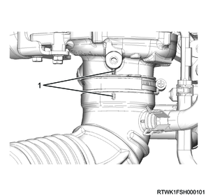
Legend
- Alignment mark
3) Install the PCV hose to the cylinder head cover and air duct.
Caution
- Align the marks on the pipe side and hose side.
Legend
- PCV hose
- Clamp
4) Install the intake air duct to the air cleaner and radiator core support.
Legend
- Intake air duct
- Clip
19. Injector installation
1) Clean the injector bracket mounting bolt holes using an air blower.
Caution
- Thoroughly clean to eliminate all sand and dust.
2) Clean the cylinder head installation surface and injector.
3) Install the gasket to the injector.
Note
- Push until seated evenly against the injector retaining nut section.
Caution
- Do not reuse the gasket.
- Do not press parts other than the gasket seal surface.

Legend
- Gasket
- Retaining nut section
- Seal surface
4) Install the injector to the cylinder head.
Caution
- Do not press the injector connector.

5) Apply engine oil to the following locations.
- Threaded section of bolt
- Seat surface of the bolt
- Washer contact surface on the injector clamp
6) Install the injector clamp to the injector.
Tightening torque: 38 N・m { 3.9 kgf・m / 28 lb・ft }
Legend
- Washer
- Injector clamp
7) Install the injector leak-off pipe to the injector.
8) Install the clips to the injector.
Caution
- Do not reuse the injector leak-off pipe or clip.
Legend
- Clip
- Injector leak-off pipe
- Injector
9) Connect the injector leak-off hose to the injector leak-off pipe and fuel leak-off pipe.
Legend
- Injector leak-off hose
10) Connect the connector to the injector.
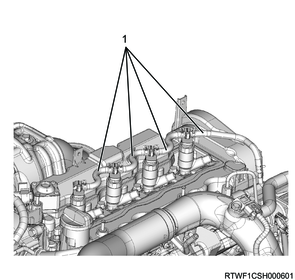
1. When replacing the injector
Erase the old cylinder number ID code on the Injector ID Code label attached to the cylinder head cover with a black pen, etc.
Label on the cylinder head cover (Sample)
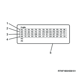
Legend
- No. 1 cylinder Injector ID Code
- No. 2 cylinder Injector ID Code
- No. 3 cylinder Injector ID Code
- No. 4 cylinder Injector ID Code
- Injector ID Code label
1) Record the Injector ID Code of the new injector.
Note
- Record the 24 characters of the injector ID plate.
The correct order of the ID codes shown in the following injector illustration is as follows.
95 04 F9 F8 F0 00 F0 E7 09 F6 F9 96
Injector (Sample)
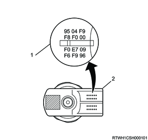
Legend
- Injector ID Code
- Injector
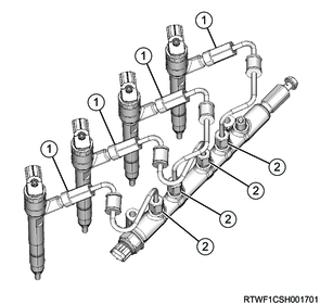
20. Injection pipe installation
1) Temporarily tighten the injection pipes to the injectors and common rail (fuel rail) in the order shown in the diagram.
Caution
- Do not reuse the injection pipe.
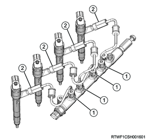
2) Final tighten the injection pipes to the injectors and common rail (fuel rail) in the order shown in the diagram.
Tightening torque: 35 N・m { 3.6 kgf・m / 26 lb・ft }