1. Component views
Inlet cover (Except for Euro2 and Euro4 specifications)
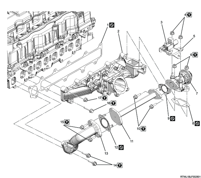
Part name
- Gasket
- Inlet cover
- Relief valve control solenoid valve
- Nut
- Relief valve control solenoid valve bracket
- Nut
- Relief valve
- Gasket
- Gasket
- Bolt
- EGR pipe
- Gasket
- EGR duct
- Bolt
- Bolt
- Bolt
- Nut
Tightening torque
4: 25 N・m { 2.5 kgf・m / 18 lb・ft }
6: 25 N・m { 2.5 kgf・m / 18 lb・ft }
10: 25 N・m { 2.5 kgf・m / 18 lb・ft }
14: 25 N・m { 2.5 kgf・m / 18 lb・ft }
15: 25 N・m { 2.5 kgf・m / 18 lb・ft }
16: 25 N・m { 2.5 kgf・m / 18 lb・ft }
17: 25 N・m { 2.5 kgf・m / 18 lb・ft }
Inlet cover (Euro2 specifications)
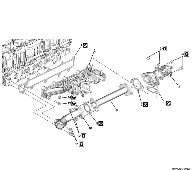
Part name
- Gasket
- Inlet cover
- Nut
- Bolt
- EGR valve
- Gasket
- Gasket
- EGR pipe
- Gasket
- EGR duct
- Bolt
- Bolt
- Bolt
- Nut
Tightening torque
3: 25 N・m { 2.5 kgf・m / 18 lb・ft }
4: 25 N・m { 2.5 kgf・m / 18 lb・ft }
11: 25 N・m { 2.5 kgf・m / 18 lb・ft }
12: 25 N・m { 2.5 kgf・m / 18 lb・ft }
13: 25 N・m { 2.5 kgf・m / 18 lb・ft }
14: 25 N・m { 2.5 kgf・m / 18 lb・ft }
Inlet cover (Euro4 specifications)
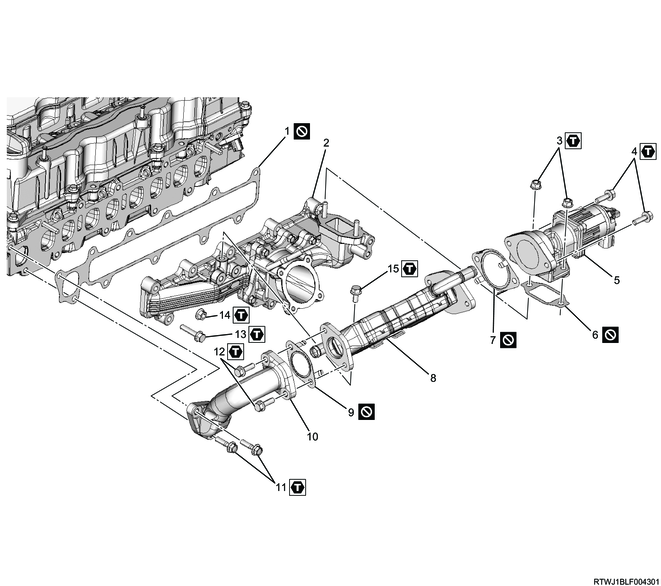
Part name
- Gasket
- Inlet cover
- Nut
- Bolt
- EGR valve
- EGR valve gasket
- EGR valve gasket
- EGR cooler
- EGR cooler gasket
- EGR duct
- Bolt
- Bolt
- Bolt
- Nut
- Bolt
Tightening torque
3: 25 N・m { 2.5 kgf・m / 18 lb・ft }
4: 25 N・m { 2.5 kgf・m / 18 lb・ft }
11: 25 N・m { 2.5 kgf・m / 18 lb・ft }
12: 25 N・m { 2.5 kgf・m / 18 lb・ft }
13: 25 N・m { 2.5 kgf・m / 18 lb・ft }
14: 25 N・m { 2.5 kgf・m / 18 lb・ft }
15: 25 N・m { 2.5 kgf・m / 18 lb・ft }
2. Generator removal
3. A/C compressor disconnect
1) Disconnect the pipe clip from the air duct bracket.
2) Disconnect the A/C compressor from the generator bracket.
Note
- Secure with wire at an appropriate position as a set with the hoses.
4. Generator bracket removal
1) Remove the generator bracket from the cylinder block.

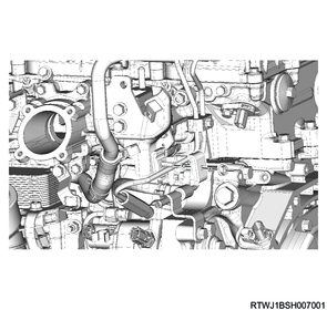
5. Intake air duct removal
1) Disconnect the connector from the boost pressure and CAC temperature sensor.
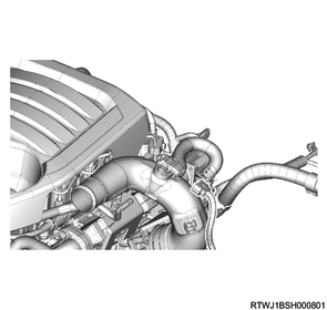
2) Remove the intake air duct from the intake throttle valve.
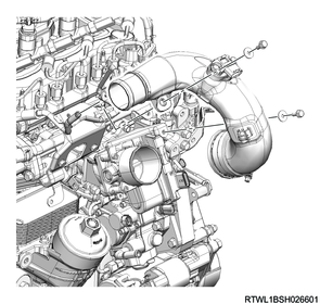
6. Intake throttle valve removal
1) Disconnect the connector from the intake throttle valve.
2) Remove the intake throttle valve and gasket from the inlet manifold.
Caution
- Do not reuse the gasket.

Legend
- Intake throttle valve
- Gasket
7. Oil level gauge guide tube removal
1) Remove the oil level gauge from the oil level gauge guide tube.
2) Remove the oil level gauge guide tube from the crankcase.
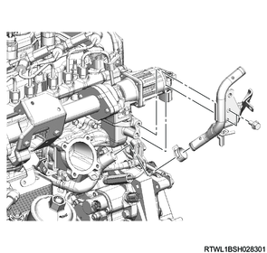
8. Water pipe removal
1. Except for Euro4 specifications
1) Disconnect the vacuum hose from the vacuum pipe.
2) Remove the vacuum pipe from the air duct bracket.
Euro2 specifications
Legend
- Vacuum pipe
- Vacuum hose
- Bracket
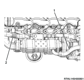
Except for Euro2 specifications
Legend
- Vacuum hose
- Vacuum pipe
- Bracket
- Relief valve control solenoid valve
- Relief valve control solenoid valve bracket
3) Remove the water hose from the water pipe.
Manual transmission models

Automatic transmission models

4) Remove the water pipe from the air duct bracket.
5) Remove the pipe clip from the water pipe.
6) Remove the water pipe from the inlet cover.
Manual transmission models
Automatic transmission models
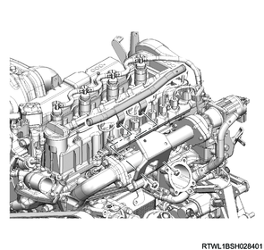
9. EGR cooler water hose disconnect
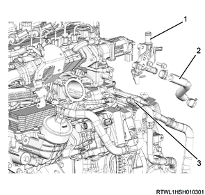
1. Euro4 specifications
1) Disconnect the EGR cooler water feed hose from the EGR cooler.
2) Disconnect the EGR cooler water return hose from the EGR cooler.
Manual transmission models
Legend
- EGR cooler water return hose
- EGR cooler water feed hose
Automatic transmission models

Legend
- EGR cooler water return hose
- EGR cooler water feed hose
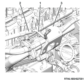
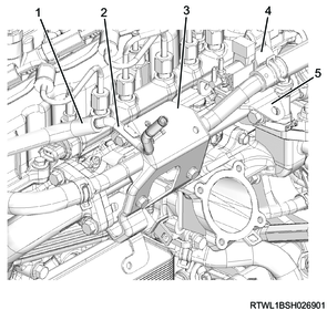
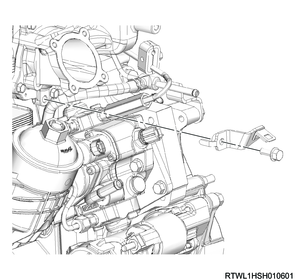
3) Disconnect the EGR cooler water hose from EGR cooler water pipe A.
4) Remove EGR cooler water pipe A from the inlet cover.
Manual transmission models

Legend
- EGR cooler water pipe A
- EGR cooler water hose
- EGR cooler water pipe B
Automatic transmission models
Legend
- EGR cooler water pipe A
- EGR cooler water hose
- Water pipe
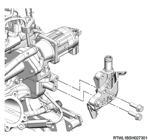
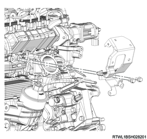
10. Relief valve removal
1. Except for Euro2 and Euro4 specifications
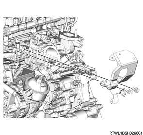
1) Remove the air duct bracket from the inlet cover.

2) Remove the harness bracket from the inlet cover.
3) Remove the following parts as a set from the cylinder head and inlet cover.
- EGR pipe
- EGR duct
- Relief valve
- Gasket
- Relief valve control solenoid valve
Caution
- Do not reuse the gasket.
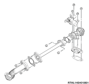
Legend
- EGR duct
- EGR pipe
- Relief valve control solenoid valve bracket
- Relief valve control solenoid valve
- Relief valve
- Gasket
Caution
- Do not reuse the gasket.
- Seal to prevent foreign material from entering.
11. EGR removal
1. Euro2 specifications
1) Remove the air duct bracket from the inlet cover.
2) Remove the harness bracket from the inlet cover.
3) Remove the following parts as a set from the cylinder head and inlet cover.
- EGR pipe
- EGR valve
- EGR duct
- Gasket

Legend
- EGR duct
- EGR pipe
- EGR valve
- Gasket
4) Remove the following parts from the EGR pipe.
- EGR valve
- EGR duct
- Gasket
Caution
- Do not reuse the gasket.
- Seal to prevent foreign material from entering.
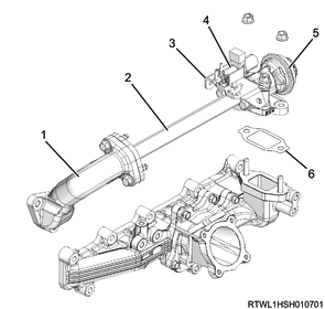
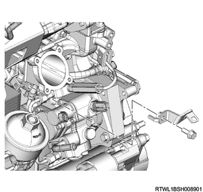
2. Euro4 specifications
1) Disconnect the vacuum hose from the vacuum pipe.
2) Remove the vacuum pipe from the bracket.

Legend
- Vacuum pipe
- Vacuum hose
- Bracket
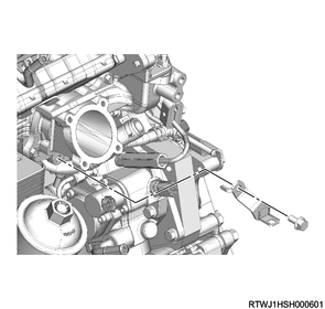
3) Remove the air duct bracket from the inlet cover.
4) Remove the harness bracket from the inlet cover.
5) Remove the following parts as a set from the cylinder head and inlet cover.
- EGR cooler
- EGR valve
- EGR duct
- Gasket
Caution
- Do not reuse the gasket.
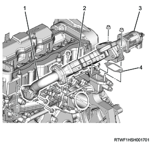
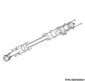
Legend
- EGR duct
- EGR cooler
- EGR valve
- Gasket
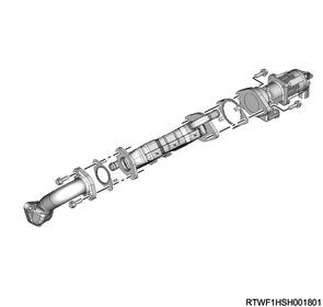
6) Remove the following parts from the EGR cooler.
- EGR valve
- EGR duct
- Gasket
Caution
- Do not reuse the gasket.
- Seal to prevent foreign material from entering.
12. Inlet cover removal
1) Remove the inlet cover from the cylinder head.
Caution
- Do not reuse the gasket.