1. Brake controls overview
1. ABS overview
The ABS is a system that prevents wheel lockup when braking and maintains the stability and maneuverability of the vehicle. If a system malfunction occurs, the fail-safe function activates, the ABS control is inhibited, and the warning light illuminates.
2. EBD overview
The EBD controls the braking force distribution of the front wheels and rear wheels according to the load status, and optimizes brake fluid pressure of the rear wheels. If a system malfunction occurs, the fail-safe function activates, EBD control is inhibited, and the warning light illuminates.
3. Brake assist control overview
The brake assist control is a system that assists in generating a strong braking force even when the brake pedal is operated weakly. If a system malfunction occurs, the fail-safe function is activated, the brake assist control is inhibited, and then the warning light illuminates.
4. TCS overview
The TCS is a system that controls engine output and braking and prevents wheel skidding during start-up. If a system malfunction occurs, the fail-safe function activates, the TCS control is inhibited, and then the warning light illuminates.
5. ESC overview
The ESC is a system that controls the braking of each wheel and the engine output when it detects an unstable vehicle condition because of a sudden vehicle posture change while the vehicle is running, and ensures the stability and steerability of the vehicle. If a system malfunction occurs, the fail-safe function activates, the ESC control is inhibited, and then the warning light illuminates.
| Running mode |
Operation of the brake control function |
|||
| ABS |
EBD |
TCS |
ESC |
|
| 2H (2WD) |
Operation |
Operation |
Operation |
Operation |
| 4H (4WD High) |
Operation |
Operation |
Operation |
Operation |
| 4L (4WD Low) |
Operation |
Operation |
Operation* |
Not in operation |
| *: Only brake control is performed, but the engine output control is not performed. |
||||
Note
- When 4L (4WD Low) is selected for the driving mode, the ESC stops operating and the TCS OFF indicator light and ESC OFF indicator light illuminate.
- The driving mode is determined by the transfer operation state that the TCCM detected.
6. Trailer sway control overview
The trailer sway control is a system that controls engine output and braking in order to maintain vehicle stability while towing a vehicle. If a system malfunction occurs, the fail-safe function is activated, the trailer sway control is inhibited, and then the warning light illuminates.
7. Hill Start Assist overview
The Hill Start Assist is a system that retains the brake pressure and prevents the vehicle from moving down, when switching from pressing down on the brake pedal to pressing down on the accelerator pedal at vehicle start on an ascending slope. If a system malfunction occurs, the fail-safe function activates, the Hill Start Assist control is inhibited, and then the warning light illuminates.
8. Hill Descent Control overview
The hill descent control is a system that ensures stability while running on a steep downslope at a fixed speed. If a system malfunction occurs, the fail-safe function is activated, the hill descent control is inhibited, and then the warning light illuminates.
9. Emergency Stop Signal (ESS) overview
The Emergency Stop Signal (ESS) is a system that rapidly flashes the rear right and rear left turn signal lights during sudden braking or during ABS operation to prevent a following vehicle from colliding. If a system malfunction occurs, the fail-safe function activates, the ESS control is inhibited, and then the warning light illuminates.
10. External braking request (AEB/ACC) overview
The external braking request is a brake control system performed by the EHCU based on a braking request from the stereo camera. If a system malfunction occurs, the fail-safe function is activated, the external braking request control is inhibited, and then the warning light illuminates.
11. Multi-collision brake (MCB) overview
The multi-collision brake (MCB) is a system that activates the brake when the airbag is deployed due to a collision, etc., and reduces a secondary collision and departure from the road. If a system malfunction occurs, the fail-safe function is activated, the multi-collision brake control is inhibited, and then the warning light illuminates.
2. Brake controls
1. ABS control
The ABS controls the brake fluid pressure appropriately by having the EHCU retain, reduce, or increase the brake fluid pressure during braking based on signals from the wheel speed sensors.
The EHCU calculates the wheel speed, wheel acceleration/deceleration, and vehicle speed using signals from the wheel speed sensors. When braking, if the wheel speed decreases so rapidly that the difference between the wheel speed and the vehicle speed becomes more than or equal to the predetermined level, the system determines that the wheels are tending toward lock-up and retains the brake pressure. The system determines that if the wheel speed decreases further in this condition, the wheels will tend toward lock-up, and thus reduces the brake fluid pressure. If afterward the system determines that locking of the wheels has been avoided, it returns to increasing, retaining or decreasing the brake fluid pressure.
2. EBD control
EBD is a system that appropriately controls braking force distribution between the front and rear according to the change of the vehicle loaded condition and the load shift caused by deceleration, and the EHCU controls the braking force distribution between the front wheels and the rear wheels during braking.
The EHCU detects the brake pedal stroke based on signals from the master cylinder pressure sensor and activates the EBD control. Once the EBD control is activated, the EHCU calculates the optimum brake force for each wheel based on signals from each wheel speed sensor and controls the hydraulic unit.

3. Brake assist control
For the brake assist control, the EHCU performs the automatic pressurization when the vehicle is suddenly braked and continues increasing the brake pressure up to the ABS operation pressure in order to maintain a high braking force. The EHCU calculates the depressing speed of the brake pedal based on signals from the master cylinder pressure sensor. During the brake assist control, as long as the brake pedal is depressed, the brake pressure increases up to the ABS operation pressure even if the depressing amount is small or constant. When the brake pedal is released, the automatic pressurization stops and the brake assist control is canceled, and then it returns to the normal brake control.
4. TCS function
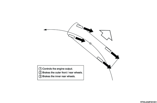
Sudden acceleration on a slippery road surface may cause the drive wheels to skid, leading to impaired startup acceleration and maneuverability. The TCS suppresses a skid by controlling the drive wheel brake and engine output and maintains the driving force appropriate for the road surface.
Note
- When 4L (4WD Low) is selected for the driving mode, only brake control on the rear side is performed, but the engine output control is not performed.
5. ESC control
Due to road conditions, vehicle speed, sudden sharp turns in the case of an emergency, external factors, etc., oversteer (strong rear wheel skidding) or understeer (strong front wheel skidding) may occur. When the ESC detects this kind of condition, it warns the driver as well as controls the brakes and the engine output of each wheel to mitigate oversteer or understeer and ensure vehicle stability.
Note
- When the 4L (4WD Low) driving mode is selected or the ESC OFF indicator light illuminates, the ESC does not operate.
1) Oversteer
If the EHCU detects oversteer, it controls the engine output and brakes mainly the outside wheels at the turning to generate moment against the turning direction, and thereby suppressing the oversteer.
2) Understeer
If the EHCU detects understeer, it controls the engine output and brakes mainly the inside wheels at the turning to generate moment in the turning direction, and thereby suppressing the understeer.
6. Rolling prevention function
When large lateral G on the vehicle is generated, and the vehicle loses stability as its gradient angle increases, this function alerts the driver and performs the engine output control and brake control. It performs the controls to decrease the vehicle speed in order to suppress the lateral G, and illuminates the stoplight.
7. Trailer sway control function (For Australia)
The EHCU detects the width of the sway transmitted from the towed vehicle at the towing vehicle side based on the signals from the yaw rate sensor, and starts the trailer sway control. If the vehicle runs at a speed of 50 km/h {31.1 mph} or more while towing a vehicle, a swaying phenomenon of the towed vehicle may occur depending on road conditions, etc. When the trailer sway control function detects this condition, it illuminates the brake lights and controls the brakes and engine output of the towing vehicle to reduce the swaying phenomenon, and ensures the vehicle stability.
8. Hill Start Assist function
The Hill Start Assist retains the brake pressure for approximately 2 seconds and prevents the vehicle from moving down, when switching from pressing down on the brake pedal to pressing down on the accelerator pedal at vehicle start on an ascending slope with an inclination of 5% or more. This function is activated as well when ascending a slope in the reverse gear and deactivated by turning the ESC OFF.
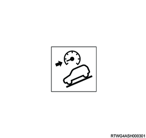
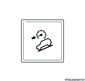
9. Hill Descent Control function
The hill descent control is a system that ensures stability while running on a steep downslope at a fixed speed. It starts operating when the accelerator pedal is released while driving at a very low speed of 30 km/h or less. The EHCU performs brake control of 4 wheels while monitoring the vehicle speed and gradient. The desired hill descent speed can be adjusted by operating the accelerator pedal or brake pedal. During the hill descent control operation, the stoplight illuminates together with the flashing of the hill descent control indicator light.
1) Hill Descent Control start conditions
- The hill descent control switch is ON. (The indicator light illuminates.)
- A steep downhill.
- The gear position is in forward (AT models: D, MT models: except R).
- The gear position is in reverse (both AT models and MT models: R).
- The vehicle speed is 30 km/h or less.
- The accelerator pedal is OFF.
- No interference from other controls and the system is normal.
2) Hill Descent Control stop conditions (system control status changes to standby status, indicator flashing to illumination)
- The gradient becomes gentle.
- The vehicle speed exceeds 30 km/h.
- The vehicle is stopped.
- Other controls interfere.
- The vehicle speed is maintained only by the engine brake.
3) Hill Descent Control system stop conditions (complete termination, indicator OFF)
- The hill descent control switch is pressed while in control or standby.
- The vehicle speed becomes 50 km/h or more while in standby.
- The system becomes hot or malfunctions.
Note
- If the system stop conditions are not met, it changes to standby mode.
10. Emergency Stop Signal (ESS) function
While the vehicle is running at a vehicle speed of 60 km/h or more, if a deceleration more than the predetermined level is detected or when the ABS is activated, the EHCU sends the ESS to the BCM via the CAN communication circuit and rapidly flashes all the turn signal lights.
1) ESS control start conditions
While the vehicle is running at a vehicle speed of 60 km/h or more, if any of the following are met, the ESS operates.
- During sudden brake (The vehicle deceleration is 6.5 m/s2 or more.)
- The ABS is activated.
2) ESS control stop conditions
After the ESS starts operating, if any of the following are met, the ESS is canceled.
- The brake pedal is released.
- The vehicle deceleration falls to 3 m/s2 or less.
- The ABS operation is stopped.
- The hazard warning flasher switch is pressed.
11. External braking request function (Models with stereo cameras)
1) Brake pressurization function
When the stereo camera determines that emergency braking is necessary, it sends a brake request to the EHCU. After the emergency braking is started, the brake fluid pressure for each of the 4 wheels is fully increased, and enhances the braking force. The stoplight illuminates while the brake pressurization function is in operation.
2) Brake retention function
When the own vehicle stops as the vehicle ahead stops while the adaptive cruise control is operating, the stereo camera sends the brake retention request to the EHCU. Based on the request from the stereo camera, the EHCU drives the valve to retain the brake fluid pressure for 2 seconds. While the brake retention function is operating, the brake operates and the stoplight illuminates even though the brake pedal is not depressed.
12. Multi-collision brake (MCB) function (Models with stereo cameras)
When the airbag is deployed due to a collision while driving, etc., the brake is operated automatically to reduce a secondary collision and departure from the road. The stoplight illuminates while the brake is operating by the multi-collision brake.
Note
- A brake with a maximum vehicle deceleration of 5 m/s2 operates by the multi-collision brake.
1) Multi-collision brake operating conditions
The multi-collision brake is activated when all of the following are met.
- Any of the airbags is deployed.
- The brake system and airbag system are normal.
- The ESC function is ON.
Note
- For models without airbags, the multi-collision brake is not activated even if a collision occurs.
2) Multi-collision brake non-operating conditions
The multi-collision brake may not be operated if any of the following is met.
- There is a malfunction in the brake system or airbag system.
- The ESC function is OFF.
3) Multi-collision brake cancellation conditions
If any of the following is met during the multi-collision brake operation, the multi-collision brake is canceled.
- The system determines that the control is complete.
- The accelerator pedal is operated.
3. EHCU operation
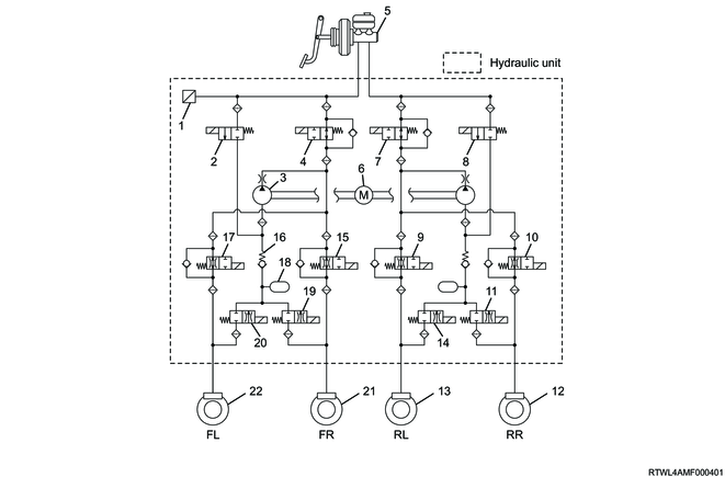
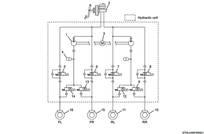
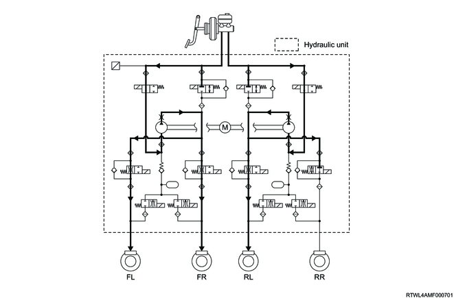
1. Hydraulic circuits diagram
<Models with stereo cameras>
Legend
- Master cylinder pressure sensor
- High pressure switching valve 1
- Dumper
- Pump
- Master cylinder cut valve 2
- Master cylinder
- Motor
- Master cylinder cut valve 1
- High pressure switching valve 2
- Rear left hold solenoid valve
- Rear right hold solenoid valve
- Rear right release solenoid valve
- Rear right brake
- Rear left brake
- Rear left release solenoid valve
- Front right hold solenoid valve
- Vacuum protection valve
- Front left hold solenoid valve
- Reservoir
- Front right release solenoid valve
- Front left release solenoid valve
- Front right brake
- Front left brake
<Except models with stereo cameras>
Models equipped with ESC
Legend
- Master cylinder pressure sensor
- High pressure switching valve 1
- Pump
- Master cylinder cut valve 2
- Master cylinder
- Motor
- Master cylinder cut valve 1
- High pressure switching valve 2
- Rear left hold solenoid valve
- Rear right hold solenoid valve
- Rear right release solenoid valve
- Rear right brake
- Rear left brake
- Rear left release solenoid valve
- Front right hold solenoid valve
- Vacuum protection valve
- Front left hold solenoid valve
- Reservoir
- Front right release solenoid valve
- Front left release solenoid valve
- Front right brake
- Front left brake
Models without ESC
Legend
- Pump
- Master cylinder
- Motor
- Reservoir
- Front left hold solenoid valve
- Front right hold solenoid valve
- Rear left hold solenoid valve
- Rear right hold solenoid valve
- Rear right release solenoid valve
- Rear right brake
- Rear left brake
- Rear left release solenoid valve
- Front right release solenoid valve
- Front left release solenoid valve
- Front right brake
- Front left brake
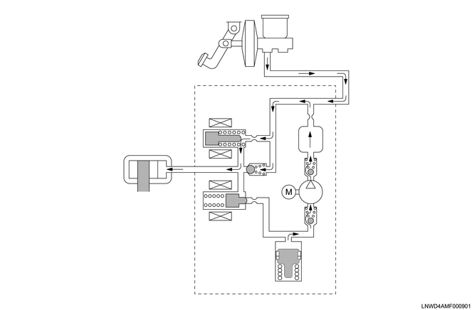
2. Normal braking
During normal braking operations, the solenoid valves are not energized, and the hold solenoid valve is opened while the release solenoid valve is closed. Brake fluid pressure passes through the hold solenoid valve and is then force-fed to the wheel cylinder.
Normal braking
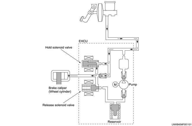
3. When the ABS is in operation
The EHCU detects sudden deceleration based on the signal from the wheel speed sensors and drives the solenoid valve of each wheel to retain, decrease, or increase the brake pressure, preventing wheel lock-up.
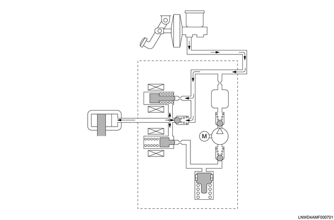
1) Brake pressure retention
When sudden deceleration signals are input from the wheel speed sensors, the hold solenoid valve closes, brake fluid from the master cylinder is cut off, and the pressure in the wheel cylinders is retained.
When retaining
2) Brake pressure decrease
When the wheels are about to lock up due to braking, the release solenoid valve is opened, and the brake fluid that has been retained in the wheel cylinders flows into the reservoir to reduce the pressure.
When pressure decreases
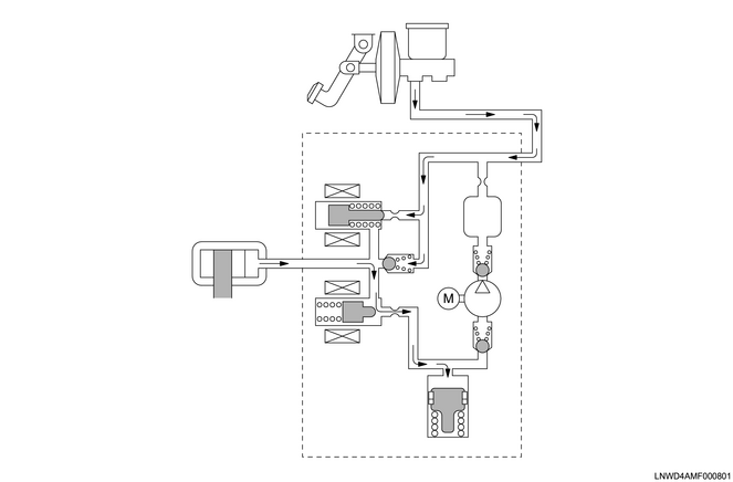
3) Brake pressure increase
When the wheel speed increases due to the pressure being reduced, the hold solenoid valve opens and the release solenoid valve closes. The brake fluid that is force-fed by the pump motor and the brake fluid from the master cylinder are force-fed to the wheel cylinders. At this time, the driver may feel a slight pulsation in the brake pedal, but this is not a malfunction. If the wheel approaches a locking state again with this pressure increase, the EHCU will repeatedly retain, decrease, and increase the fluid pressure.
When pressure increases
| Valve operating condition |
When not controlled |
During ABS control |
||
| Hold mode |
Depressurization mode |
Pressurization mode |
||
| Hold solenoid valve |
Open |
Close |
Close |
Open |
| Release solenoid valve |
Close |
Close |
Open |
Close |
4. During TCS operation (Models equipped with ESC)
The TCS control applies the brake by leading hydraulic pressure generated in the pump in the hydraulic unit into the wheel cylinder of the driving wheel and prevents slippage of the vehicle wheel due to driving force.
2WD
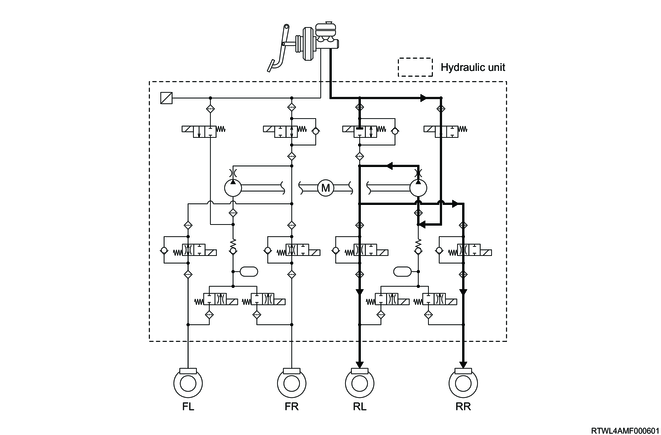
4WD
| Valve operating condition |
When not controlled |
TCS control |
|||
| Pressurization mode |
Hold mode |
Depressurization mode |
|||
| Master cylinder cut valve 1 |
Open |
Regulated |
Regulated |
Regulated |
|
| Master cylinder cut valve 2 |
Open |
Regulated |
Regulated |
Regulated |
|
| MAX oil pressure wheel for 2-wheel control in the same system, or control wheel for 1-wheel control in the same system |
Hold solenoid valve |
Open |
Open |
Open |
Open |
| Release solenoid valve |
Close |
Close |
Close |
Close |
|
| MIN oil pressure wheel for 2-wheel control in the same system |
Hold solenoid valve |
Open |
Open |
Close |
Close |
| Release solenoid valve |
Close |
Close |
Close |
Open |
|
| Non-control wheel |
Hold solenoid valve |
Open |
Close |
Close |
Close |
| Release solenoid valve |
Close |
Close |
Close |
Close |
|
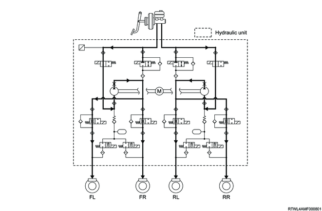
5. During ESC operation (Models equipped with ESC)
1) In case of the over steer
The brakes are operated by the hydraulic pressure generated by the pump inside the hydraulic unit being guided into the wheel cylinder of each wheel, controlling the side skidding of the rear wheels.
In the case of oversteering, the front and rear wheel brakes on the outer side of the turn are operated.
2) In case of the under steer
The brakes are operated by the hydraulic pressure generated by the pump inside the hydraulic unit being guided into the wheel cylinder of each wheel, controlling the side skidding of the front wheels.
In the case of understeer, the brakes of both rear wheels, or if necessary, the brakes of the front wheel outside of the turn are activated.
As an example, the illustration shows the front left/right brakes and the rear left brake as the controlled wheels, with the rear right brake as the uncontrolled wheel.
| Valve operating condition |
During ESC control |
||||
| Pressurization mode |
Hold mode |
Depressurization mode |
|||
| Control system |
Master cylinder cut valve |
Close |
Close |
Close |
|
| Control wheel |
Hold solenoid valve |
Open |
Close |
Close |
|
| Release solenoid valve |
Close |
Close |
Open |
||
| Control wheel |
Hold solenoid valve |
Open |
Close |
Close |
|
| Release solenoid valve |
Close |
Close |
Open |
||
| Control system (Diagonal wheels) |
Master cylinder cut valve |
Close |
Close |
Close |
|
| Control wheel |
Hold solenoid valve |
Open |
Close |
Close |
|
| Release solenoid valve |
Close |
Close |
Open |
||
| Non-control wheel |
Hold solenoid valve |
Close |
Close |
Close |
|
| Release solenoid valve |
Open |
Open |
Open |
||
4. Brake controls components
1. Wheel speed sensor
The wheel speed sensor uses a Hall IC sensor. The wheel speed sensor for the front wheels is installed to the knuckles, and the wheel speed sensor for the rear wheels is installed to the rear axle case. Voltage is generated in the sensor by the rotation of the front and rear wheels. The frequency of this voltage changes proportionately with the rotation speed, thereby enabling the wheel speed to be detected.
Front side
Rear side
2. Steering angle sensor (Models equipped with ESC)
The steering angle sensor is installed to the combination switch and it detects the steering angle and steering direction. The signal detected by the steering angle sensor is sent to the EHCU via the CAN communication circuit.
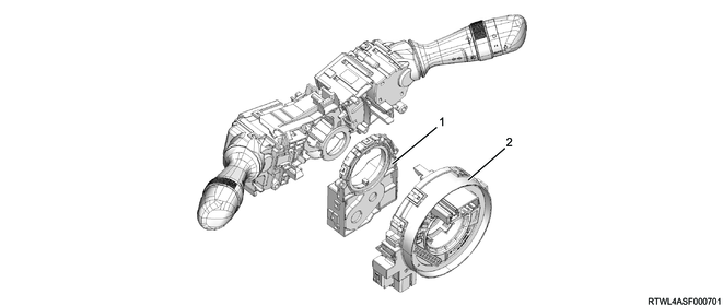
Legend
- Steering angle sensor
- Combination switch
3. Yaw rate sensor (Models equipped with ESC)
The yaw rate sensor is comprised of the semiconductor-type yaw rate sensor and G sensor, and is built into the EHCU. It detects rotating angular speed and lateral acceleration speed due to the changes in vehicle behavior, and sends them to the EHCU.
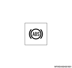
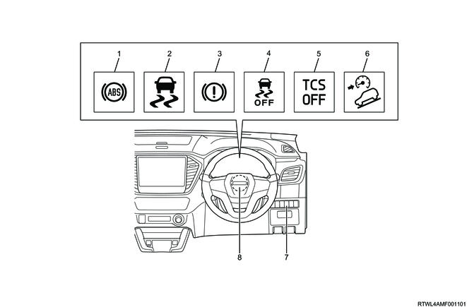
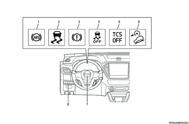
4. ABS warning light
The ABS warning light notifies the driver of an ABS malfunction. When the EHCU detects an ABS malfunction through the self-diagnosis function, it illuminates the ABS warning light.
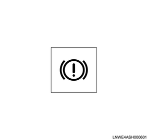
5. Brake system warning light
The brake system warning light notifies the driver of an EBD malfunction. It also illuminates if the brake fluid level gets low or other brake-related abnormal conditions are detected.
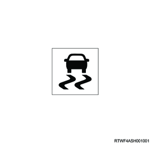
6. ESC warning light (Models equipped with ESC)
The ESC warning light informs the driver of an ESC malfunction. When the EHCU detects an ESC malfunction through the self-diagnosis function, it illuminates the ESC warning light. The ESC warning light flashes during TCS, ESC, or trailer sway control operation.
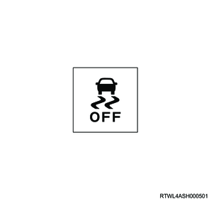
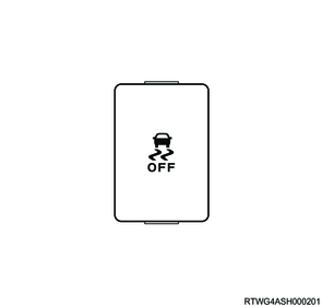
7. ESC OFF indicator light (Models equipped with ESC)
When the ESC operation is stopped while the ESC OFF switch is being operated or the 4L (4WD Low) is selected, the ESC OFF indicator light illuminates.
8. TCS OFF indicator light (Models equipped with ESC)
When the TCS operation is stopped while the ESC OFF switch is being operated or the 4L (4WD Low) is selected, the TCS OFF indicator light illuminates.

9. Hill descent control indicator light (Models equipped with ESC)
The hill descent control indicator light illuminates when the system is in a standby status, and flashes when the system is in operation.
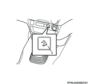
10. Hill descent control switch (Models equipped with ESC)
The hill descent control switch turns the hill descent control function ON/OFF.
11. ESC OFF switch (Models equipped with ESC)
In an attempt to escape from mud, etc., depressing the accelerator with the TCS or ESC operating may limit the driving force and make the escape difficult. The TCS and ESC can be deactivated by operating the ESC OFF switch.
1) When 2H (2WD) or 4H (4WD High) is selected for the driving mode
Briefly pushing the ESC OFF switch will switch the TCS to TCS OFF mode, deactivating the TCS. Also, the TCS OFF indication light in the instrument panel cluster illuminates at this time.
Pressing and holding the ESC OFF switch for about 5 seconds or more with the vehicle stopped switches the ESC to ESC OFF mode, deactivating the TCS and ESC. Also, the TCS OFF indicator light and ESC OFF indicator light in the instrument panel cluster illuminate at this time.
Each mode can be canceled by pressing the ESC OFF switch briefly or turning the ignition switch OFF.
2) When 4L (4WD Low) is selected for the driving mode
The ESC function stops operating.
Pressing and holding the ESC OFF switch for about 5 seconds or more with the vehicle stopped switches the TCS to TCS OFF mode, deactivating the TCS. Also, the TCS OFF indicator light and ESC OFF indicator light in the instrument panel cluster illuminate at this time.
The TCS OFF mode can be canceled by pressing the ESC OFF switch briefly or turning the ignition switch OFF.
Note
- When the ESC OFF switch is pressed and held for 10 seconds or more, it returns to normal mode.
| Running mode |
ESC OFF switch operation |
Control allowed/prohibited |
Indication light |
||||
| Engine TCS |
Brake TCS |
Engine ESC |
Brake ESC |
TCS OFF |
ESC OFF |
||
| 2H (2WD), 4H (4WD High) |
No |
Permission |
Permission |
Permission |
Permission |
OFF |
OFF |
| Short press |
Inhibition |
Permission |
Inhibition |
Permission |
Illuminated |
OFF |
|
| Long press (5 seconds or longer) |
Inhibition |
Inhibition |
Inhibition |
Inhibition |
Illuminated |
Illuminated |
|
| 4L (4WD Low) |
No |
Inhibition |
Permission |
Inhibition |
Inhibition |
Illuminated |
Illuminated |
| Short press |
Inhibition |
Permission |
Inhibition |
Inhibition |
Illuminated |
Illuminated |
|
| Long press (5 seconds or longer) |
Inhibition |
Inhibition |
Inhibition |
Inhibition |
Illuminated |
Illuminated |
|
Note
- When the rear differential lock is in operation, all the above controls are stopped.
12. Rear differential lock switch
The rear differential lock switch switches the differential lock between activation and deactivation.

When the rear differential lock switch is turned ON, the following brake controls are deactivated and the warning light and indicator light are illuminated.
<Brake control not to be operated>
- Anti-lock Brake System (ABS)
- Electronic Stability Control (ESC)
- Traction Control System (TCS)
- Trailer sway control
- Hill Start Assist
- Hill Descent Control
- Emergency Stop Signal (ESS)
<Warning light/indicator light to be illuminated>
- ABS warning light
- ESC warning light
- ESC OFF indicator light
- TCS OFF indication light
13. EHCU
The EHCU consists of the control unit part and hydraulic unit part. The control unit is comprised of a brake control part, malfunction detection part, and fail-safe part. It drives the hydraulic unit, etc., based on signals from the various sensors. If a malfunction occurs in the system, it has the ability to inhibit each function using the fail-safe function. Using the self-diagnosis function, it also displays defective areas when performing trouble diagnosis. The hydraulic unit is comprised of the motor, pump, solenoid valves, reservoir, and master cylinder pressure sensor, etc.
1) Solenoid valve
When the brake fluid pressure is retained, reduces, or increases, the oil passage is switched.
2) Reservoir
The brake fluid is stored when pressure decreases.
3) Pump
The brake fluid stored in the reservoir is force-fed to the master cylinder.
4) Motor
The pump is driven.
5) Master cylinder pressure sensor
The master cylinder brake fluid pressure is detected.
EHCU

5. Brake controls component views
1. External component location diagram
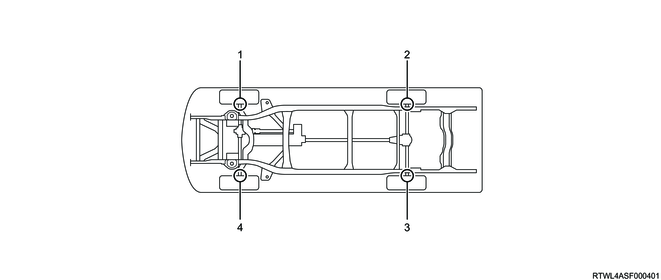
Legend
- Front right wheel speed sensor
- Rear right wheel speed sensor
- Rear left wheel speed sensor
- Front left wheel speed sensor
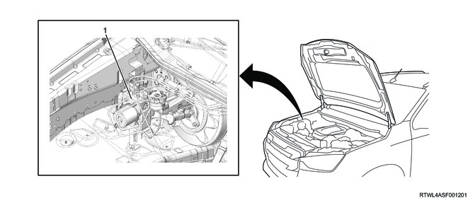
Legend
- EHCU
2. Internal component location diagram
RHD models
Legend
- ABS warning light
- ESC warning light (Models equipped with ESC)
- Brake system warning light
- ESC OFF indicator light (Models equipped with ESC)
- TCS OFF indicator light (Models equipped with ESC)
- Hill descent control indicator light (Models equipped with ESC)
- ESC OFF switch (Models equipped with ESC)
- Steering angle sensor (Models equipped with ESC)
LHD models
Legend
- ABS warning light
- ESC warning light (Models equipped with ESC)
- Brake system warning light
- ESC OFF indicator light (Models equipped with ESC)
- TCS OFF indicator light (Models equipped with ESC)
- Hill descent control indicator light (Models equipped with ESC)
- Steering angle sensor (Models equipped with ESC)
- ESC OFF switch (Models equipped with ESC)
Note
- The illustration shows an RHD model.
Bench seat type
Legend
- Hill descent control switch (Models equipped with ESC)
RHD models (Except bench seat type)

Legend
- Parking aid system OFF switch
- Hill descent control switch (Models equipped with ESC)
- Rear differential lock switch
LHD models (Except bench seat type)
Legend
- Rear differential lock switch
- Hill descent control switch (Models equipped with ESC)
- Parking aid system OFF switch
6. Brake system
1. Braking device system diagram
ABS specifications and ESC specifications

2. Master cylinder and brake booster
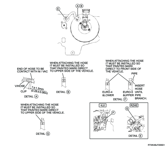
3. Vacuum hose
Caution
- When attaching the vacuum hose, make sure the arrow painted on the hose is pointing to the engine side.
Legend
- Engine side
- Check valve
RHD models
LHD models
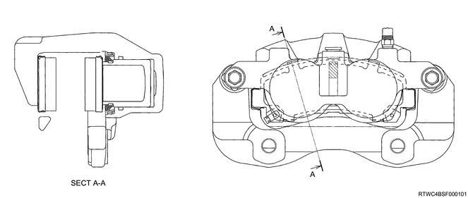
4. Front disc brake
5. Rear drum brake
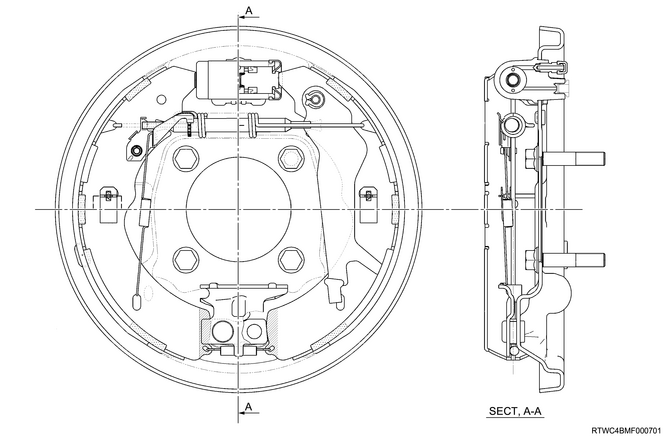
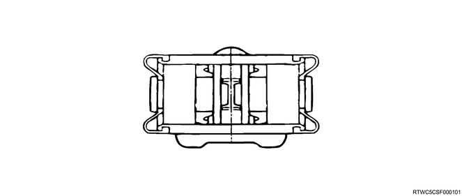
6. Rear wheel cylinder
7. General circuit diagram
1. EHCU general circuit diagram
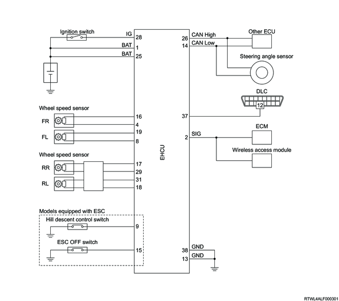
2. EHCU terminal layout
| Pin No. |
Pin Function |
| 1 |
BAT (Motor power supply) |
| 2 |
Vehicle speed signal |
| 3 |
- |
| 4 |
FR Wheel speed sensor (-) |
| 5 |
- |
| 6 |
- |
| 7 |
- |
| 8 |
FL Wheel speed sensor (-) |
| 9 |
Hill descent control switch |
| 10 |
- |
| 11 |
- |
| 12 |
- |
| 13 |
GND (Ground) |
| 14 |
CAN Low |
| 15 |
ESC OFF switch |
| 16 |
FR Wheel speed sensor (+) |
| 17 |
RR Wheel speed sensor (+) |
| 18 |
RL Wheel speed sensor (-) |
| 19 |
FL Wheel speed sensor (+) |
| 20 |
- |
| 21 |
- |
| 22 |
- |
| 23 |
- |
| 24 |
- |
| 25 |
BAT (Valve power supply) |
| 26 |
CAN High |
| 27 |
- |
| 28 |
IG (ignition voltage) |
| 29 |
RR Wheel speed sensor (-) |
| 30 |
- |
| 31 |
RL Wheel speed sensor (+) |
| 32 |
- |
| 33 |
- |
| 34 |
- |
| 35 |
- |
| 36 |
- |
| 37 |
DLC |
| 38 |
GND (Ground) |