1. Automatic transmission control system overview
The AWR6B45 automatic transmission is a 6-speed electronically-controlled automatic transmission with manual mode. The automatic transmission is controlled by the TCM and controls the following.
- Shift control
- Lock-up control
- Transmission fluid pressure control
- Garage control
- Running mode control
- Engine torque control
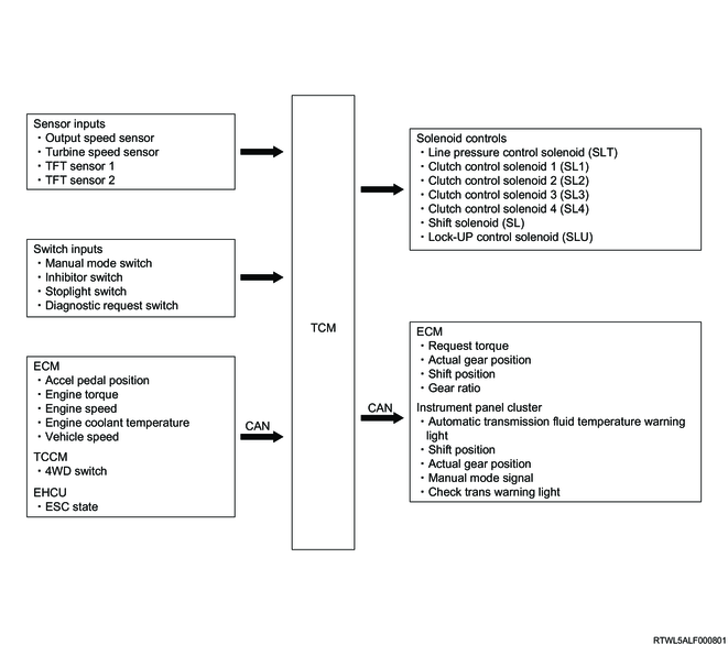
The TCM determines the vehicle driving situation or driver's intentions based on input signals from sensors, switches, etc., to perform optimum control. The TCM electrically controls solenoids and the automatic transmission therefore shifts gears. The operation state is fed back to the TCM based on the solenoid, sensor and switch signals.
2. Shift control
1. Automatic gearshift control
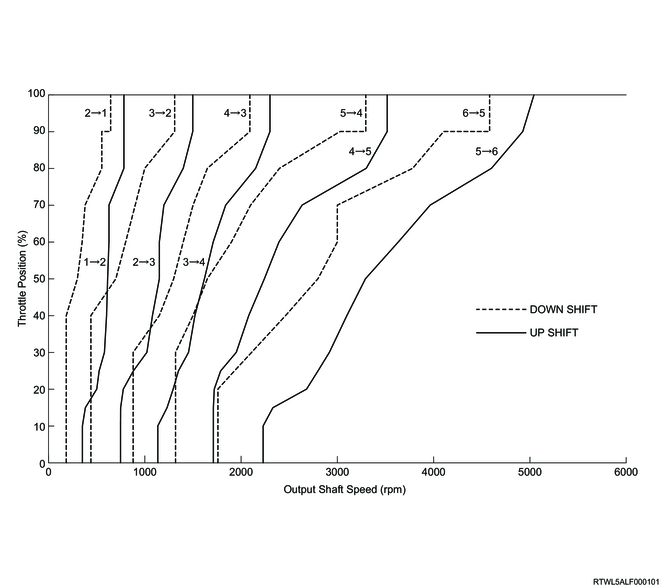
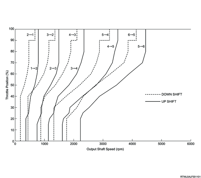
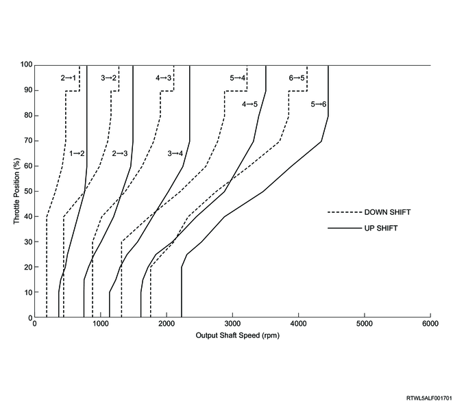
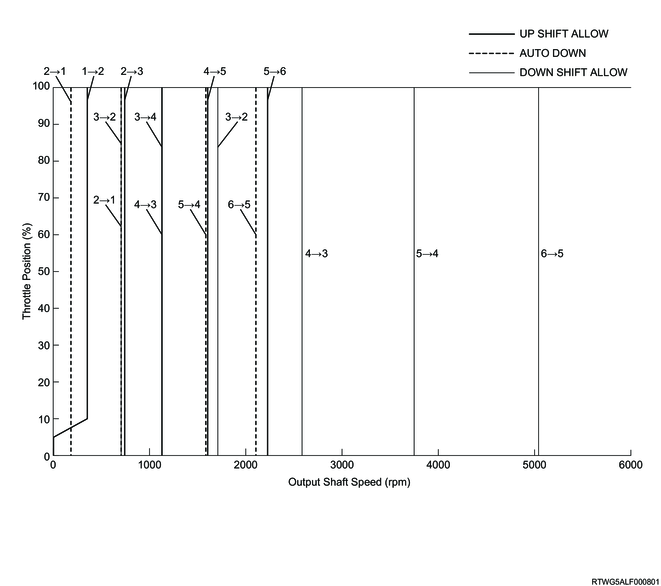
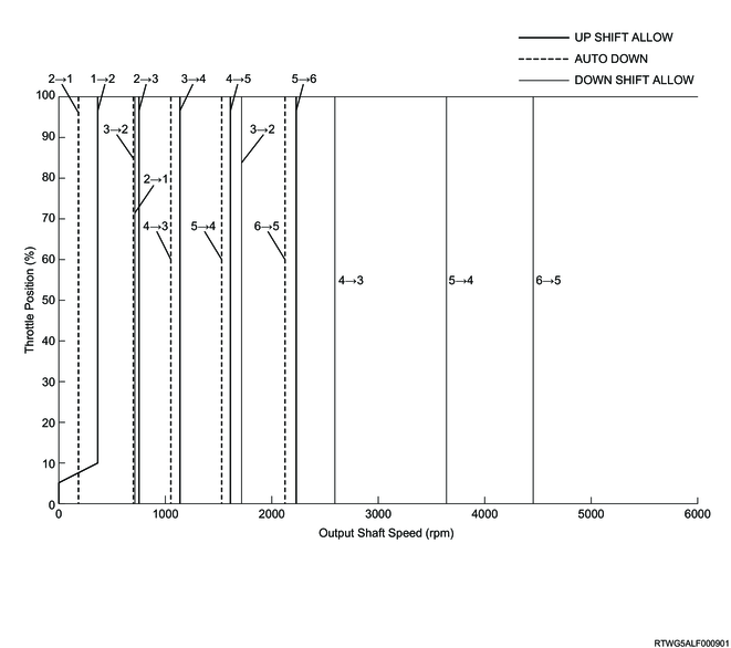
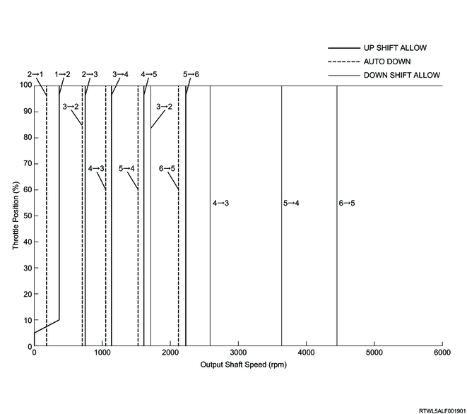
The TCM selects the optimum shift map in response to input signals, and perform shift control based on the shift map. The TCM optimally controls each solenoid during shifting to reduce shifting shock when accelerating and decelerating. In addition, when a malfunction of the automatic transmission system is detected based on information from solenoids and sensors, the TCM controls to inhibit shifting.
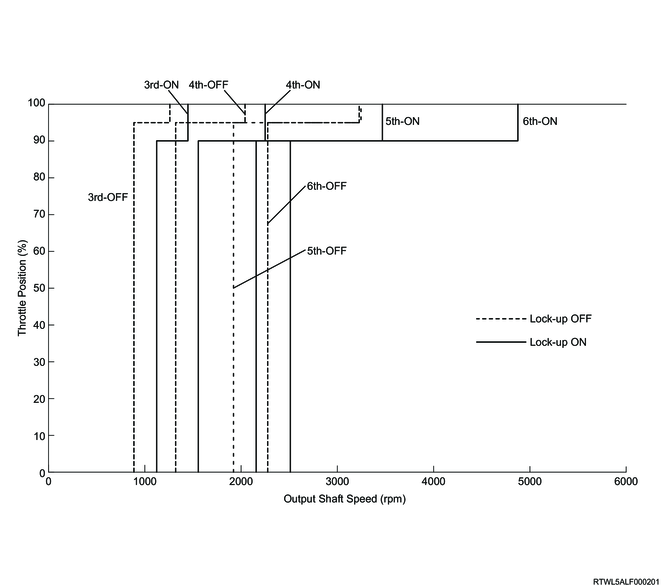
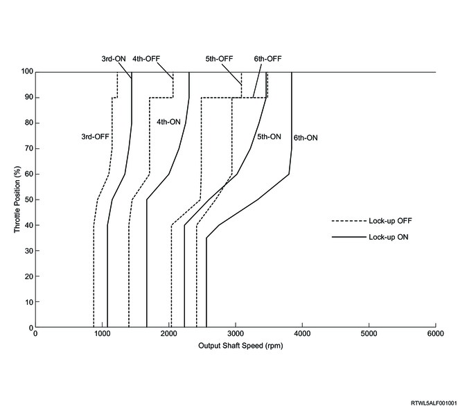
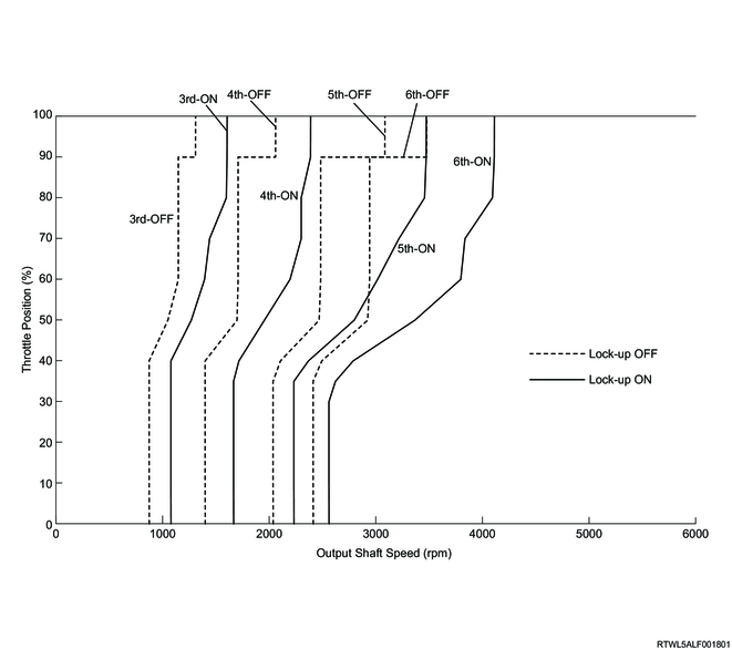
In normal mode, the following shift schedule is used.
D-range normal shift pattern (RZ4E engine models)
D-range normal shift pattern (4JJ3 with DPD)
D-range normal shift pattern (4JJ3 without DPD)
2. Skip gear shift control
If the TCM determines that the skip gear shift to the 2nd or higher is possible based on the calculated desired gear, it skips the gear position in between and shifts to the desired gear.
3. Lock-up control
1. Lock-up timing control
The TCM performs lock-up control according to the selected shift map. If the TCM determines the lock-up point from input signals, it controls the lock-up control solenoid (SLU) and engages the lock-up clutch. Lock-up is activated normally when the gear is 3rd or higher.
In normal mode and manual mode, the following shift schedule is used for lock-up timing.
D range normal mode and manual mode lock-up timing (RZ4E engine models)
D-range normal mode and manual mode lock-up timing (4JJ3 with DPD)
D-range normal mode and manual mode lock-up timing (4JJ3 without DPD)
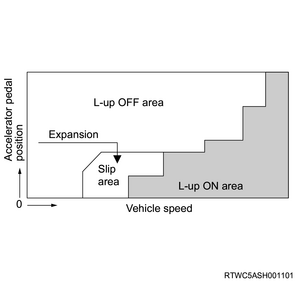
2. Slip lock-up control
The TCM does not engage the lock-up clutch completely but slightly slips within the lock-up OFF region when accelerating to further enlarge the lock-up region up to the low-speed range, and prevent the engine speed from increasing, resulting in fuel economy improvement. In addition, slippage of the lock-up clutch allows the torque converter to absorb vibration from the engine. When decelerating, slippage of the lock-up clutch during coasting at 3rd gear or higher increases the engine speed, cuts the idle fuel injection, and improves fuel efficiency.
4. Transmission fluid pressure control
1. Line pressure control
In order to improve shift feeling, the TCM determines required line pressure according to the shifting operation state, various input signals, and engine torque information, and controls the line pressure control solenoid (SLT) in accordance with the oil pressure.
2. Clutch-to-clutch pressure control
When the vehicle is running in the 2nd gear or higher, the TCM operates each clutch control solenoid (SL1, SL2, SL3, SL4) based on the operation state, various input signals, and engine torque information, in order to directly control the oil pressure of the clutches and brakes, resulting in shock reduction when shifting. In addition, the oil pressure of previous shifting is reflected by self-learning control to optimize shifting characteristics.
3. Clutch pressure optimum control
The TCM calculates the optimum turbine torque based on signals from various sensors, and precisely controls the line pressure by activating each clutch control solenoid (SL1, SL2, SL3, SL4) and line pressure control solenoid (SLT), resulting in shock reduction when shifting. In addition, the rate of turbine speed change is maintained to optimize shifting characteristics through self-learning control.
5. Garage control
1. Garage shift control
When the selector lever is shifted from the N position to the D position, or from the N position to the R position after the engine start, the TCM controls the oil pressure applied to C1 clutch and B1 brake by activating the clutch control solenoids (SL1, SL4), and provides appropriate oil pressure to reduce shock when shifting.
2. Reverse lock-out control
When the vehicle is running forward at the predetermined speed or more, and the TCM detects an operation to the R position due to an error, the TCM controls shift solenoid (SL) and clutch control solenoid (SL4) and shifts to neutral in order to prevent danger and protect the transmission.
6. Running mode control
1. Driving mode switching control
The TCM selects from among the following driving modes depending on the driving situation.
- Normal mode
- Manual mode
- L4 mode
- Hot 1 mode
- Cruise control mode
- Up slope 1 mode
- Up slope 2 mode
- Downslope mode
- Warm-up mode (4JJ3 engine models)
The driving mode is selected automatically based on driving conditions, except for manual mode and L4 mode, and usually selects normal mode. The driving mode is set according to the following priorities. From each driving mode, the TCM selects the appropriate mode for the driving conditions.
Manual mode > L4 mode > Hot 1 mode > Cruise control mode > Upslope 2 mode > Upslope 1 mode > Warm-up mode > Normal mode
1) Normal mode
This mode is selected when the selector lever is in the D position and when other priority mode conditions are not met.
2) Manual mode
When the selector lever is moved from the D position to the right and the TCM receives the manual select switch signal, this mode is selected.
3) L4 mode
When 4L of the 4WD switch is selected and the TCM receives the 4L switch signal from the TCCM, this mode is selected.
4) Hot 1 mode
This mode is selected to protect the transmission when ATF temperature becomes high.
5) Cruise control mode
When the cruise control main switch is turned ON and the TCM receives cruise signals from the ECM, this mode is selected.
6) Upslope 1 mode, Upslope 2 mode
This mode is selected when the TCM detects that the vehicle is running on an upslope.
7) Downslope mode
This mode is selected when the TCM detects that the vehicle is running on a downslope.
8) Warm-up mode (4JJ3 engine models)
This mode is selected when the engine coolant temperature is low.
2. Sequential control
When the selector lever is operated from the D position to the right and the TCM receives the manual select switch signal, the mode switches to manual mode. In manual mode, the driver can select a desired gear by operating the selector lever to the upshift (+) position or downshift (-) position. To protect the transmission, however, if the vehicle speed is more (or less) than the specified value, the TCM does not perform manual mode shift operation but automatically shifts the gear.
When the manual mode is selected, the following shift schedule is used.
Manual mode normal shift pattern (RZ4E engine models)
Manual mode normal shift pattern (4JJ3 with DPD)
Manual mode normal shift pattern (4JJ3 without DPD)
3. L4 mode control
If the TCM receives the 4L switch signals from the TCCM via the CAN communication circuit, it switches to L4 mode. In L4 mode, shifting to the 5th or 6th gear is inhibited and lock-up control is not performed in order to prevent transmission gear overrunning.
4. Hot mode control
If the ATF temperature reaches the specified value or more, the TCM switches to hot mode to prevent the ATF temperature from increasing. In the hot mode, shifting to the low-speed gear is performed in order to prevent oil temperature increase due to torque converter slip, and early use of lock-up decreases the ATF temperature and engine coolant temperature.
5. Cruise control
When the TCM detects the cruise control state from the ECM via the CAN communication circuit, it switches to cruise control mode and maintains the vehicle speed.
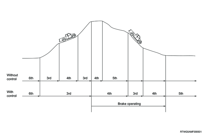
6. Slope control
If the TCM detects that the vehicle is running on an upslope, it switches to the upslope mode in order to prevent frequent shiftdown and shiftup and achieve sufficient torque. In addition, if it detects that the vehicle is running on a downslope, it switches to the downslope mode to prevent shifting up caused by acceleration when the accelerator is released.
7. Warm-up control (4JJ3 engine models)
The TCM switches the shift map to warm up mode to improve operability when the engine coolant temperature is low.
8. 2nd start control
Selecting the 2nd gear when the vehicle starts or accelerates on a slippery road, etc., allows smooth starting operation.
The 2nd start control can be performed only when the manual mode is selected.
7. Engine torque control
The TCM outputs torque request signals to the ECM via the CAN communication circuit in order to reduce shifting shock caused by engine torque during shifting. Based on signals from the TCM, the ECM reduces engine torque by controlling the fuel injection, etc. In addition, the TCM controls the line pressure at the same time, which can result in a reduction in shifting shock.
8. Emergency mode
The TCM switches to emergency mode to protect the automatic transmission when the specified DTC is set. The emergency mode varies its control depending on the failure location.
9. Starter inhibitor control
The starter inhibitor circuits are installed to automatic transmission models, and the selector lever is designed to prevent the starter from operating in a position other than the N or P position. When the selector lever is operated to the N or P position, the neutral switch on the starter relay circuit is closed and the circuit is grounded, and the starter relay therefore operates in the circuit only if the selector lever is in the N or P position.

10. Select mechanism
1. Selector lever unit
The selector lever unit switches between forward and reverse or between manual mode and normal mode.
The selector lever unit is equipped with a manual mode switch to detect forward and reverse movement and left and right movement of the lever. The TCM detects the operation status of the selector lever from each switch signal. When the selector lever is operated from the N position to the D position, the TCM performs shift control in normal mode. When the lever is operated from the D position to the right, the TCM switches to manual mode and performs shift control in accordance with the driver's selector lever operation in the direction towards the upshift or downshift position. When the selector lever is operated to the D position in manual mode, the mode switches to normal mode, and when the selector lever is operated from the D position to the right in normal mode, the mode switches to manual mode but stays in the current gear.
The selector lever unit is also equipped with a shift lock function. When the selector lever is operated to the P position, the shift lock solenoid is activated, and it cannot be operated to the R position unless the brake pedal is depressed.
The selector lever is operated to the P position to close the shift lock control switch, and the interlock controller thereby detects the P position. When the interlock controller detects the P position, it brings electrical contact with the shift lock solenoid. If ON signal is input from the stoplight switch to the interlock controller, the shift lock solenoid energization is stopped, releasing the shift lock.
Note
- The illustration shows an RHD model.
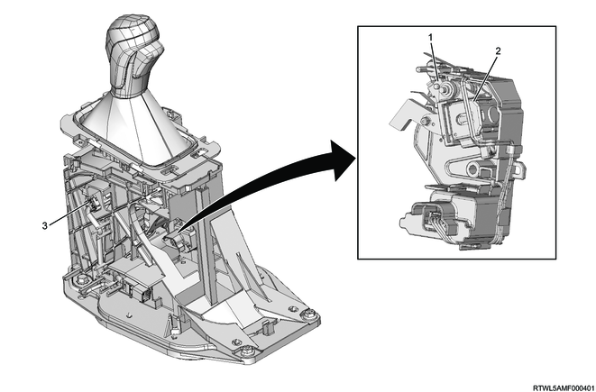
Legend
- Shift lock solenoid
- Shift lock control switch
- Manual mode switch
2. Key interlock mechanism (with Keyless Entry)
The key interlock mechanism is installed to automatic transmission models, and it does not allow the key to be removed when the shift position is other than the P position in order to prevent parking with the selector lever in a position other than the P position.
The key interlock mechanism consists of the interlock controller installed to the selector lever, shift lock control switch, and key interlock unit installed to the steering lock assembly.
If the selector lever is in a position other than the P position, the shift lock control switch is open, the interlock controller does not energize the key interlock unit, and the key cannot be set to the LOCK position.
When the selector lever is in the P position, the shift lock control switch is closed, the interlock controller energizes the key interlock unit, and the key can be set to the LOCK position.
Note
- The illustration shows an RHD model.
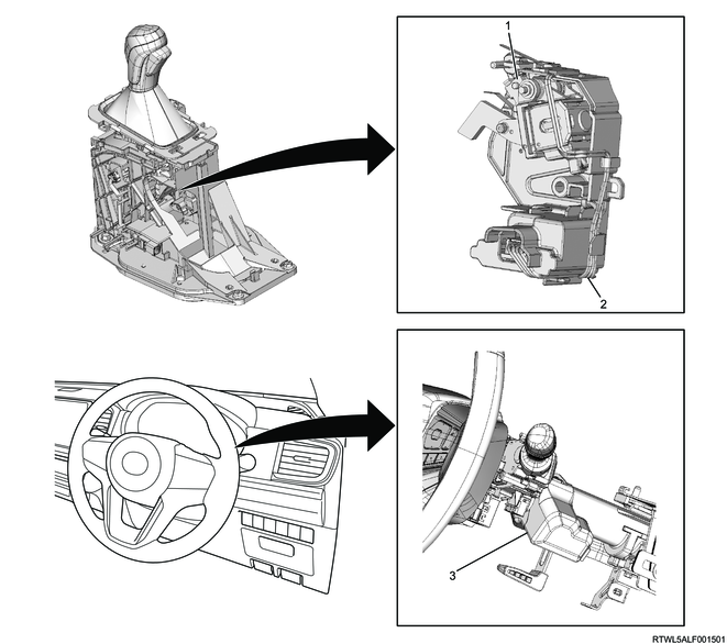
Legend
- Shift lock control switch
- Interlock controller assembly
- Key interlock unit
3. Key interlock mechanism (with Passive Entry and Start System)
The key interlock mechanism is installed to automatic transmission models, and it does not allow the power mode to be turned OFF when the shift position is other than the P position in order to prevent parking with the selector lever in a position other than the P position.
The key interlock mechanism consists of the interlock controller installed to the selector lever, shift lock control switch, and wireless access module.
If the selector lever is in a position other than the P position, the shift lock control switch is opened, and the interlock controller does not ground the parking signal from the wireless access module, thereby the power mode cannot be turned OFF.
If the selector lever is in the P position, the shift lock control switch is closed, and the interlock controller grounds the parking signal from the wireless access module, thereby the power mode can be turned OFF.
Note
- The illustration shows an RHD model.
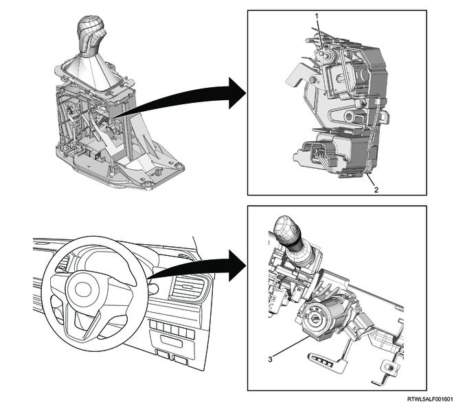
Legend
- Shift lock control switch
- Interlock controller assembly
- Key interlock unit
11. Automatic transmission
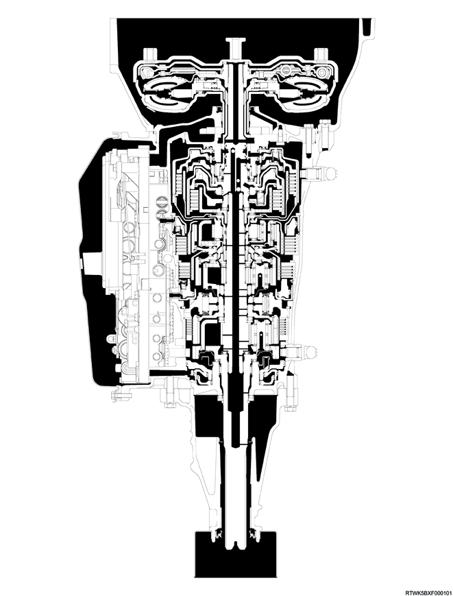
1. AWR6B45 automatic transmission
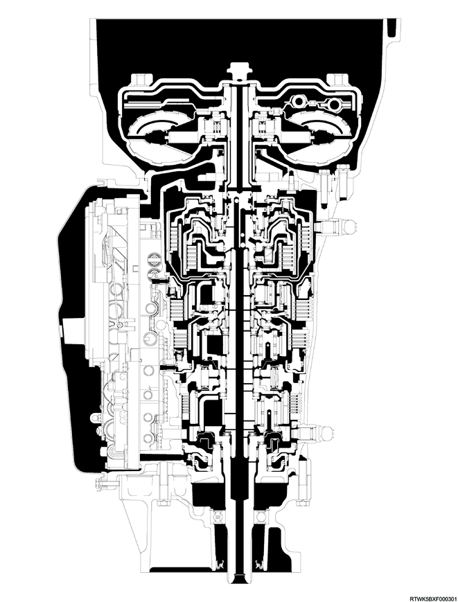
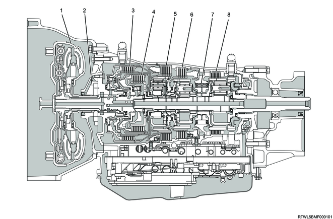
This automatic transmission is an electronically-controlled forward 6-speed automatic transmission. It adopts high-precision clutch oil pressure control system to achieve a smooth and high-response shift feeling.
Cross-sectional diagram (2WD models, RZ4E-TC equipped models)
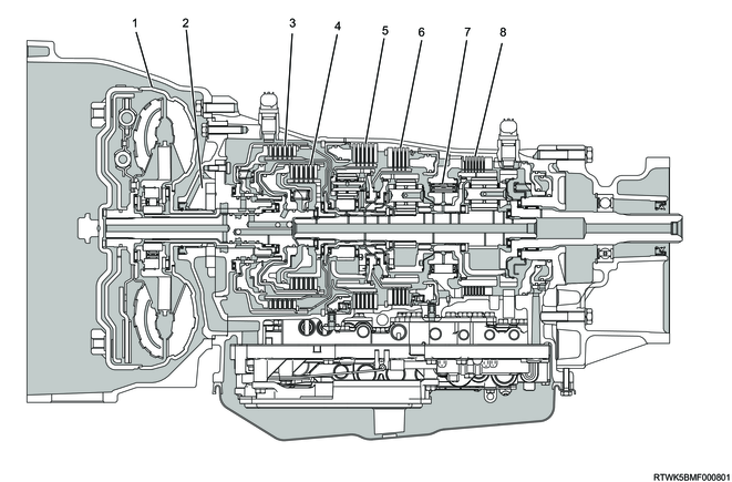
Cross-sectional diagram (2WD models, 4JJ3 equipped models)
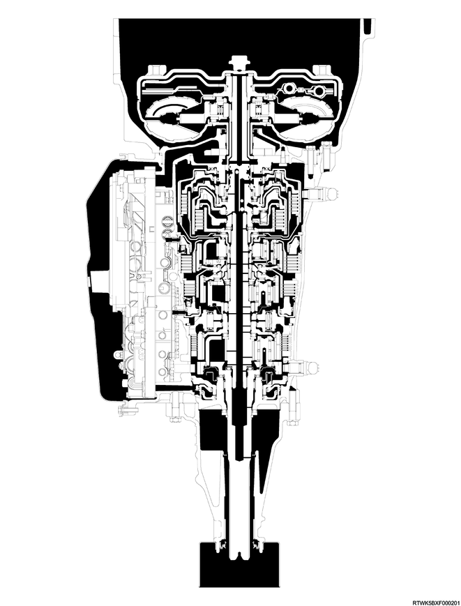
Cross-sectional diagram (4WD models, RZ4E-TC equipped models)
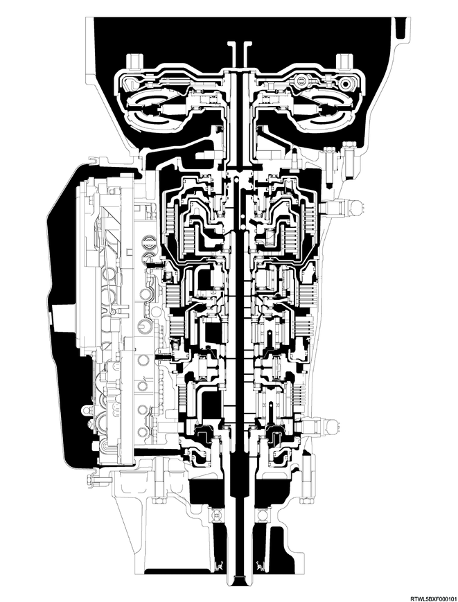
Cross-sectional diagram (4WD models, 4JJ3 equipped models)
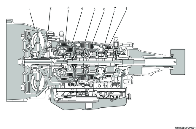
Cross-sectional structure diagram (2WD models, RZ4E-TC equipped models)

Legend
- Torque converter
- Oil pump
- Clutch No. 2
- Clutch No. 1
- Brake No. 2
- Brake No. 1
- One-way clutch No. 3
- Brake No. 4
Cross-sectional structure diagram (2WD models, 4JJ3 equipped models)
Legend
- Torque converter
- Oil pump
- Clutch No. 2
- Clutch No. 1
- Brake No. 2
- Brake No. 1
- One-way clutch No. 3
- Brake No. 4
Cross-sectional structure diagram (4WD models, RZ4E-TC equipped models)
Legend
- Torque converter
- Oil pump
- Clutch No. 2
- Clutch No. 1
- Brake No. 2
- Brake No. 1
- One-way clutch No. 3
- Brake No. 4
Cross-sectional structure diagram (4WD models, 4JJ3 equipped models)
Legend
- Torque converter
- Oil pump
- Clutch No. 2
- Clutch No. 1
- Brake No. 2
- Brake No. 1
- One-way clutch No. 3
- Brake No. 4
This automatic transmission adopts oil level adjustment mechanism with the overflow plug. This mechanism consists of the filler plug, overflow plug, transmission fluid temperature sensor, and check trans warning light.
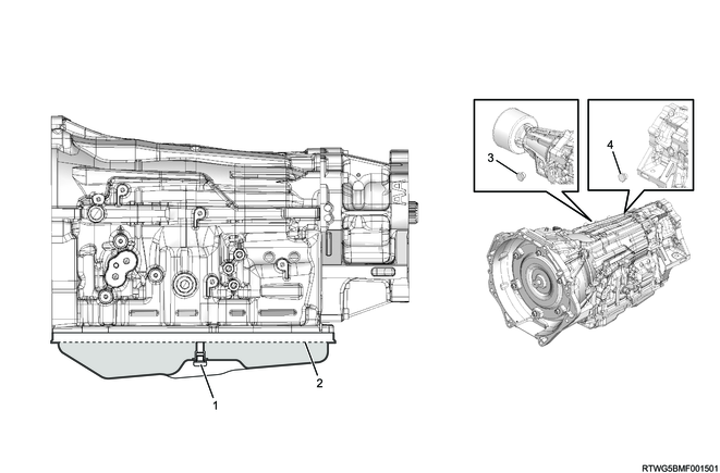
Legend
- Overflow plug
- Proper level
- Filler plug (2WD model)
- Filler plug (4WD model)
2. Torque converter
The torque converter consists of the following parts.
- Converter housing
- Pump impeller
- Turbine runner
- Stator
- 1-way clutch
- Lock-up clutch
The torque converter transmits engine power to the transmission, and the ATF within transmits and amplifies the torque. In addition, activating the lock-up clutch will directly connect the engine and transmission and increase the transmission efficiency, which improves fuel efficiency. The torque converter used is 3-element, 1-stage, and 2-phase type. "1-stage" means one turbine runner, "2-phase" means that the turbine runner serves as a torque converter when the turbine runner slowly rotates in proportion to the pump impeller, and that the turbine runner serves as fluid coupling when the turbine runner rapidly rotates in proportion to the pump impeller.
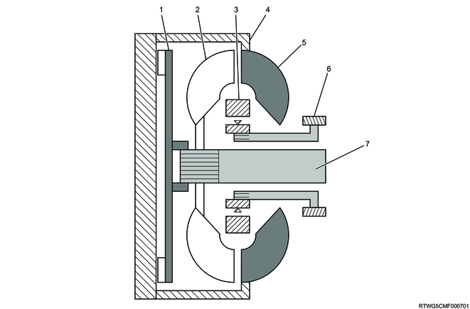
Legend
- Lock-up piston
- Turbine runner
- Stator
- Converter case
- Pump impeller
- Oil pump
- Input shaft
3. Oil pump
High-performance and lightweight oil pump is used for the AWR6B45 automatic transmission. The drive gear is installed coaxially with the torque converter extension sleeve, and rotates in the direction of engine rotation. As a result, the oil pump body rotates to pressurize and discharge ATF.
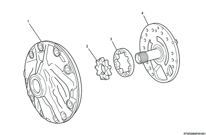
Legend
- Oil pump body
- Drive gear
- Driven gear
- Stator shaft assembly
4. ATF cooler/warmer
The ATF cooler/warmer is installed at the lower left of the converter housing. The ATF cooler/warmer is installed on the engine coolant circuit to allow use of the waste heat from the engine, thereby enabling a quick ATF temperature rising when the engine is started with the engine cold. It can reduce the friction loss of the transmission and improve the fuel efficiency. In addition, when the ATF temperature exceeds the engine coolant temperature, it serves as an ATF cooling circuit.
ATF cooler/warmer circuit diagram
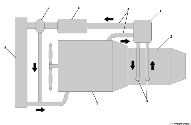
Legend
- ATF cooler/warmer
- Transmission
- ATF circuit
- Engine coolant circuit
- Engine
- EGR cooler, etc.
- Thermostat
- Radiator
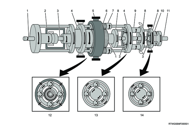
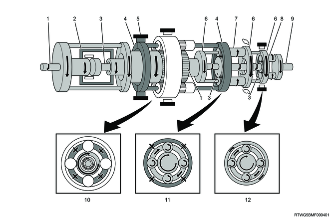
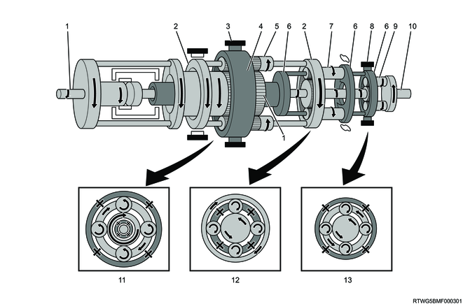
12. Power transmission
The AWR6B45 automatic transmission has a combination of 3 pairs of planetary gears, 2 pairs of multi-plate clutches, 3 pairs of multi-disc brakes, and 1 pair of one-way clutches, which composes 6-speed forward gears and 1-speed reverse gear.
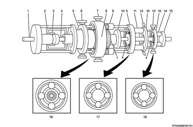
Legend
- Input shaft, front sun gear
- Clutch No. 2
- Clutch No. 1
- Intermediate shaft, middle sun gear, rear sun gear
- Front planetary carrier, middle ring gear
- Brake No.2
- Brake No. 1
- Front ring gear
- Front planetary pinion gear
- Middle planetary carrier, rear ring gear
- Middle planetary pinion gear
- 1-way clutch No. 3
- Brake No. 4
- Rear planetary pinion gear
- Output shaft
- Front planetary gear
- Middle planetary gear
- Rear planetary gear
| Clutch, brake engagement control |
|||||||
| Selector lever position |
Gear position |
C1 |
C2 |
B1 |
B2 |
B4 |
F3 |
| P |
- |
||||||
| R |
Reverse |
O |
O |
||||
| N |
- |
||||||
| D |
1st |
O |
O |
||||
| 2nd |
O |
O |
|||||
| 3rd |
O |
O |
|||||
| 4th |
O |
O |
|||||
| 5th |
O |
O |
|||||
| 6th |
O |
O |
|||||
| M |
1st |
O |
|||||
| 1st (Engine brake) |
O |
O |
|||||
| 2nd |
O |
O |
|||||
| 3rd |
O |
O |
|||||
| 4th |
O |
O |
|||||
| 5th |
O |
O |
O |
||||
| 6th |
|||||||
| O: Engaged |
|||||||
| Functions of the clutch and brake |
||
| Part name |
Symbol |
Function |
| Clutch No. 1 |
C1 |
Connects the input shaft and the intermediate shaft. |
| Clutch No. 2 |
C2 |
Connects the input shaft and the middle planetary gear. |
| Brake No. 1 |
B1 |
The front ring gear is fixed. |
| Brake No. 2 |
B2 |
The rotation of the front planetary carrier and middle ring gear are fixed. |
| Brake No. 4 |
B4 |
The rear ring gear is fixed. |
| One-way clutch No. 3 |
F3 |
The middle planetary carrier and rear ring gear are fixed to the counterclockwise rotation. |
Note
- The rotational direction indicates the state viewed from the front of the vehicle.
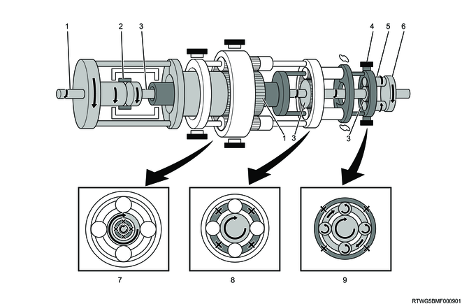
D-range 1st gear
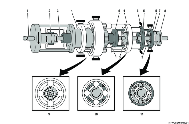
Legend
- Input shaft, front sun gear
- Clutch No. 1
- Intermediate shaft, middle sun gear, rear sun gear
- Front planetary carrier, middle ring gear
- Middle planetary carrier, rear ring gear
- 1-way clutch No. 3
- Rear planetary pinion gear
- Output shaft
- Front planetary gear
- Middle planetary gear
- Rear planetary gear
Manual mode 1st gear (At engine braking)
Legend
- Input shaft, front sun gear
- Clutch No. 1
- Intermediate shaft, middle sun gear, rear sun gear
- Brake No. 4
- Rear planetary pinion gear
- Output shaft
- Front planetary gear
- Middle planetary gear
- Rear planetary gear
D-range 2nd gear
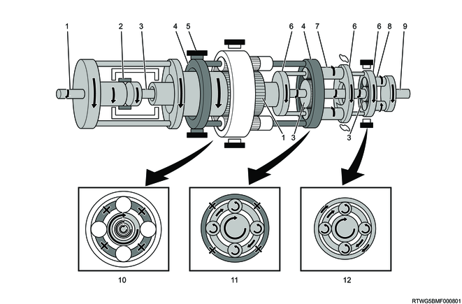
Legend
- Input shaft, front sun gear
- Clutch No. 1
- Intermediate shaft, middle sun gear, rear sun gear
- Front planetary carrier, middle ring gear
- Brake No.2
- Middle planetary carrier, rear ring gear
- Middle planetary pinion gear
- Rear planetary pinion gear
- Output shaft
- Front planetary gear
- Middle planetary gear
- Rear planetary gear
D-range 3rd gear
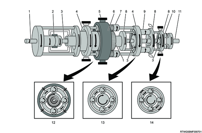
Legend
- Input shaft, front sun gear
- Clutch No. 1
- Intermediate shaft, middle sun gear, rear sun gear
- Front planetary carrier, middle ring gear
- Brake No. 1
- Front ring gear
- Front planetary pinion gear
- Middle planetary carrier, rear ring gear
- Middle planetary pinion gear
- Rear planetary pinion gear
- Output shaft
- Front planetary gear
- Middle planetary gear
- Rear planetary gear
D-range 4th gear
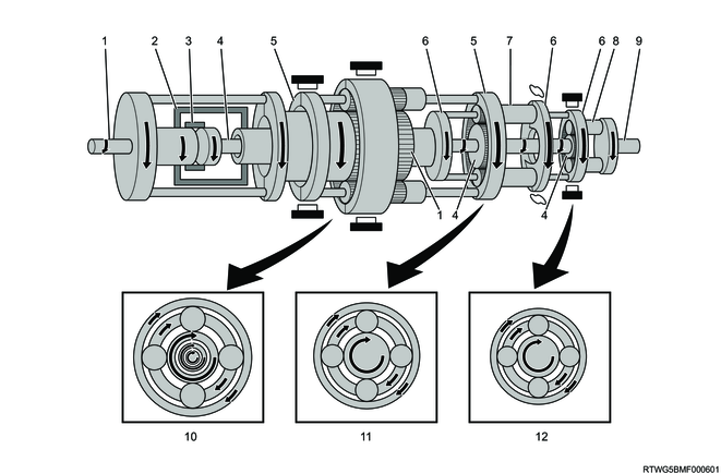
Legend
- Input shaft, front sun gear
- Clutch No. 2
- Clutch No. 1
- Intermediate shaft, middle sun gear, rear sun gear
- Front planetary carrier, middle ring gear
- Middle planetary carrier, rear ring gear
- Middle planetary pinion gear
- Rear planetary pinion gear
- Output shaft
- Front planetary gear
- Middle planetary gear
- Rear planetary gear
D-range 5th gear
Legend
- Input shaft, front sun gear
- Clutch No. 2
- Intermediate shaft, middle sun gear, rear sun gear
- Front planetary carrier, middle ring gear
- Brake No. 1
- Front ring gear
- Front planetary pinion gear
- Middle planetary carrier, rear ring gear
- Middle planetary pinion gear
- Rear planetary pinion gear
- Output shaft
- Front planetary gear
- Middle planetary gear
- Rear planetary gear
D range 6th gear
Legend
- Input shaft, front sun gear
- Clutch No. 2
- Intermediate shaft, middle sun gear, rear sun gear
- Front planetary carrier, middle ring gear
- Brake No.2
- Middle planetary carrier, rear ring gear
- Middle planetary pinion gear
- Rear planetary pinion gear
- Output shaft
- Front planetary gear
- Middle planetary gear
- Rear planetary gear
R-range
Legend
- Input shaft, front sun gear
- Front planetary carrier, middle ring gear
- Brake No. 1
- Front ring gear
- Front planetary pinion gear
- Middle planetary carrier, rear ring gear
- Middle planetary pinion gear
- Brake No. 4
- Rear planetary pinion gear
- Output shaft
- Front planetary gear
- Middle planetary gear
- Rear planetary gear
13. Transmission controls components
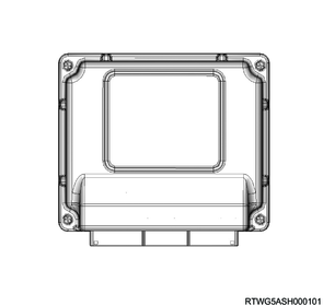
1. TCM
The TCM is installed inside the passenger side instrument panel. The TCM controls the system based on the information sent from various sensors and switches. When a system malfunction occurs, the TCM informs the driver via the flashing of the check trans warning light and sets the DTC. Also, the TCM stops some system functions or performs fail-safe control.
2. Inhibitor switch
The inhibitor switches are installed to the right side of the transmission, and detect the P, R, N, and D positions of the selector lever. When the selector lever is shifted to any of the P, R, N, and D positions, the applicable switch of the inhibitor switch is turned ON. A part of the inhibitor switch circuit is connected to the starter circuit, which enables engine start using only the P or N range.
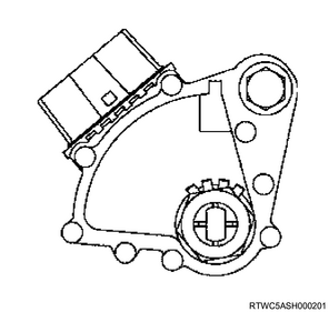
3. Output speed sensor
The output speed sensor detects rotation of the parking lock gear installed to the rear planetary gear assembly. The output speed sensor is a Hall element type sensor that generates pulse signals using the gear rotation. The TCM calculates the vehicle speed using the output speed sensor signal.
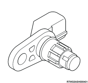
4. Turbine speed sensor
The turbine speed sensor detects the rotation of the direct clutch assembly and forward clutch assembly. The turbine speed sensor is a Hall element type sensor that generates pulse signals using the gear rotation. The TCM calculates the input shaft speed based on the turbine speed sensor signal.
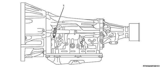
5. Transmission fluid temperature sensor
Transmission fluid temperature sensors 1 and 2 are installed on the valve body together with the internal harness inside the transmission, and detects the ATF temperature inside the valve body. The transmission fluid temperature sensor is a thermistor and its resistance changes according to the ATF temperature. When the temperature is higher, the resistance becomes smaller; while the sensor output voltage becomes lower. Transmission fluid temperature sensor 1 detects the temperature of the oil pressure line, and transmission fluid temperature sensor 2 detects the temperature of the cooler line.

Legend
- Transmission fluid temperature sensor 1
- Transmission fluid temperature sensor 2
6. Solenoid
The AWR6B45 automatic transmission uses the following 7 solenoids installed in the valve body, and controls the oil pressure in the transmission.
- Shift solenoid (SL)
- Clutch control solenoid (SL1, SL2, SL3, SL4)
- Line pressure control solenoid (SLT)
- Lock-up control solenoid (SLU)
The solenoid valve switches the oil pressure supply circuit to the clutch and brakes. The TCM controls each solenoid as follows in accordance with the desired gear.
| Solenoids operation |
|||||||
| Selector lever position |
Gear position |
SL |
SL1 |
SL2 |
SL3 |
SL4 |
SLU |
| P |
- |
MIN |
MIN |
MIN |
MIN |
MIN |
OFF |
| R |
Reverse |
MIN |
MIN |
MIN |
MIN |
MAX |
OFF |
| N |
- |
MIN |
MIN |
MIN |
MIN |
MIN |
OFF |
| D |
1st |
MIN |
MAX |
MIN |
MIN |
MIN |
OFF |
| 2nd |
ON |
MAX |
MIN |
MAX |
MIN |
OFF |
|
| 3rd |
ON |
MAX |
MIN |
MIN |
MAX |
OFF |
|
| 4th |
ON |
MAX |
MAX |
MIN |
MIN |
OFF |
|
| 5th |
ON |
MIN |
MAX |
MIN |
MAX |
OFF |
|
| 6th |
ON |
MIN |
MAX |
MAX |
MIN |
OFF |
|
| M |
1st |
MIN |
MAX |
MIN |
MIN |
MIN |
ON |
| 2nd |
ON |
MAX |
MIN |
MAX |
MIN |
OFF |
|
| 3rd |
ON |
MAX |
MIN |
MIN |
MAX |
OFF |
|
| 4th |
ON |
MAX |
MAX |
MIN |
MIN |
OFF |
|
| 5th |
ON |
MIN |
MAX |
MIN |
MAX |
OFF |
|
| 6th |
ON |
MIN |
MAX |
MAX |
MIN |
OFF |
|
| ON: The control voltage is supplied OFF: The control voltage is not supplied MIN: The control current is lower MAX: The control current is higher |
|||||||
1) Shift solenoid (SL)
Shift solenoid (SL) is turned ON and OFF based on the control signal from the TCM, and thereby switches the oil path in the valve. It releases the lock-up forcibly by switching the oil path in the valve, to prevent engine stall or perform reverse lock-out control.
2) Clutch control solenoid (SL1, SL2, SL3, SL4)
Clutch control solenoids (SL1, SL2, SL3, SL4) open and close the oil path linearly according to the control current from the TCM, and controls the oil pressure to clutches (C1, C2) and brakes (B1, B2). The TCM performs shifting from 1st to 6th by controlling each clutch control solenoid.
3) Line pressure control solenoid (SLT)
Line pressure control solenoid (SLT) opens and closes the oil path linearly according to the control current from the TCM, and regulates the oil pressure supplied from the oil pump.
4) Lock-up control solenoid (SLU)
Lock-up control solenoid (SLU) opens and closes the oil path linearly according to the control current from the TCM, based on the engine speed, accelerator pedal opening position, turbine speed, and output speed, and preforms lock-up control and slip control.

Legend
- Shift solenoid (SL)
- Clutch control solenoid (SL4)
- Lock-up control solenoid (SLU)
- Clutch control solenoid (SL3)
- Clutch control solenoid (SL1)
- Clutch control solenoid (SL2)
- Line pressure control solenoid (SLT)
7. Check trans warning light
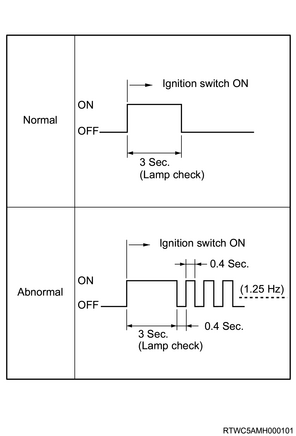
The check trans warning light notifies the driver of a transmission control system malfunction. The check trans warning light illuminates for 3 seconds when the ignition switch is turned to ON, and then turns OFF. If the TCM sets a DTC, the check trans warning light is flashed.
Check trans warning light illumination or flashing pattern
8. Automatic transmission fluid temperature warning light
The automatic transmission fluid temperature warning light notifies the driver of high ATF temperature. The automatic transmission fluid temperature warning light illuminates for 3 seconds when the ignition switch is turned to ON, and then turns OFF. When the TCM detects that the ATF temperature is 150°C {302°F} or more based on the signal from the transmission fluid temperature sensor installed to the transmission, the TCM illuminates the automatic transmission fluid temperature warning light via the CAN communication circuit.
9. Shift indicator
The shift indicator informs the driver of the selector lever position. The instrument panel cluster receives the selector lever position from the TCM via the CAN communication circuit, and it is displayed on the shift indicator. The shift indicator displays D if the vehicle runs in normal mode with the selector lever in the D position, while the shift indicator displays the selected gear if the vehicle runs in manual mode when the selector lever is operated from the D position to the right.

14. Transmission controls component views
Legend
- Turbine speed sensor

Legend
- Output speed sensor
- Inhibitor switch
Note
- The illustration shows an RHD model.
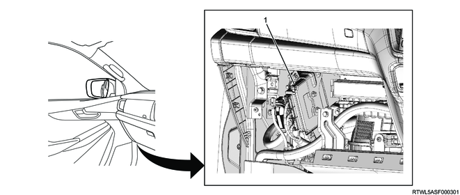
Legend
- TCM
15. General circuit diagram
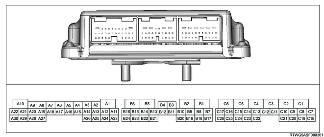
1. TCM schematic circuit diagram

2. TCM pin assignment
| No. |
Pin Function |
| 1 |
Ground |
| 2 |
Clutch control solenoid 2 (SL2) low side control |
| 3 |
Clutch control solenoid 2 (SL2) high side control |
| 4 |
Line pressure control solenoid (SLT) low side control |
| 5 |
Line pressure control solenoid (SLT) high side control |
| 6 |
Lock-UP control solenoid 1(SLU) low side control |
| 7 |
Lock-UP control solenoid 1(SLU) high side control |
| 8 |
Clutch control solenoid 1 (SL1) low side control |
| 9 |
Clutch control solenoid 1 (SL1) high side control |
| 10 |
Battery voltage |
| 11 |
- |
| 12 |
- |
| 13 |
- |
| 14 |
- |
| 15 |
- |
| 16 |
- |
| 17 |
- |
| 18 |
- |
| 19 |
- |
| 20 |
- |
| 21 |
Ignition voltage |
| 22 |
- |
| 23 |
TFT sensor 1 signal |
| 24 |
TFT sensor 1 low reference |
| 25 |
TFT sensor 2 low reference |
| 26 |
TFT sensor 2 signal |
| 27 |
- |
| 28 |
Shift solenoid (SL) control |
| 29 |
- |
| 30 |
- |
| No. |
Pin Function |
| 1 |
Output speed sensor high |
| 2 |
Output speed sensor low |
| 3 |
- |
| 4 |
- |
| 5 |
Clutch control solenoid 4 (SL4) low side control |
| 6 |
Clutch control solenoid 3 (SL3) low side control |
| 7 |
Turbine speed sensor high |
| 8 |
Turbine speed sensor low |
| 9 |
- |
| 10 |
- |
| 11 |
- |
| 12 |
- |
| 13 |
- |
| 14 |
Clutch control solenoid 4 (SL4) high side control |
| 15 |
- |
| 16 |
Clutch control solenoid 3 (SL3) high side control |
| 17 |
- |
| 18 |
- |
| 19 |
- |
| 20 |
- |
| 21 |
- |
| 22 |
- |
| 23 |
- |
| 24 |
- |
| No. |
Pin Function |
| 1 |
CAN high signal |
| 2 |
CAN low signal |
| 3 |
- |
| 4 |
- |
| 5 |
Stoplight switch signal |
| 6 |
N position switch signal |
| 7 |
- |
| 8 |
- |
| 9 |
- |
| 10 |
- |
| 11 |
- |
| 12 |
- |
| 13 |
- |
| 14 |
Up shift switch signal |
| 15 |
- |
| 16 |
D position switch signal |
| 17 |
R position switch signal |
| 18 |
Diagnostic request switch |
| 19 |
- |
| 20 |
Down shift switch signal |
| 21 |
- |
| 22 |
- |
| 23 |
- |
| 24 |
Manual select switch signal |
| 25 |
- |
| 26 |
P position switch signal |
16. Transmission identification plate
ID plate, Serial Number of Transmission
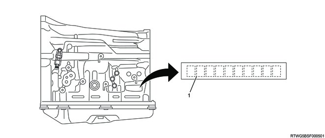
Legend
- Serial Number
ID plate, Serial Number of TCM
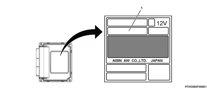
Legend
- Serial Number