DTC P2091:00 [SKYACTIV-G 2.0, SKYACTIV-G 2.5]


id0102h4010000

Caution
•  Vehicle specifications differ depending on the vehicle identification number (VIN).
―  Type A VIN:
JM0 KE****** 100001—
JM6 KE****** 100001—
JM7 KE****** 100001—
JM8 KE****** 100001—
JMZ KE****** 100001—
KE10** 100001—
―  Type B VIN:
JM0 KE****** 200001—
JM6 KE****** 200001—
JM8 KE****** 200001—
JMZ KE****** 200001—
KE10** 200001—

DTC P2091:00

OCV circuit high input

DETECTION CONDITION
Type A VIN
•  The PCM monitors the OCV current. If the PCM detects that the OCV control current (calculated from the OCV) is above the specification current, the PCM determines that the OCV circuit has a malfunction.
Type B VIN
•  The OCV control voltage relative to the PCM control is too high.
Diagnostic support note
•  This is a continuous monitor (CCM).
•  The check engine light illuminates if the PCM detects the above malfunction condition during the first drive cycle.
•  FREEZE FRAME DATA (Mode 2)/Snapshot data is available.
•  DTC is stored in the PCM memory.
FAIL-SAFE FUNCTION
Type A VIN
•  Performs the exhaust variable valve timing control with a maximum cam retard request.
Type B VIN
•  Set the exhaust variable valve timing control to the maximum advanced position.
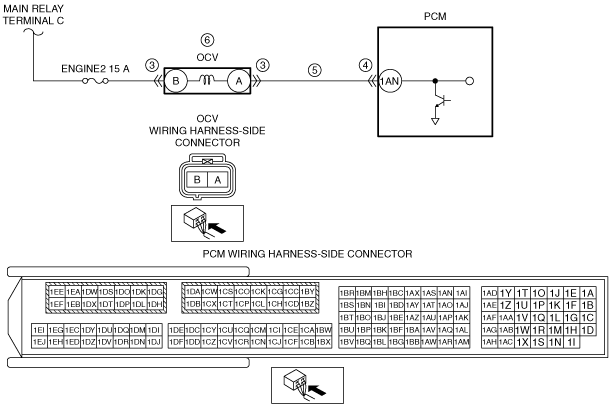
POSSIBLE CAUSE
•  OCV connector or terminals malfunction
•  PCM connector or terminals malfunction
•  Short to power supply in wiring harness between OCV terminal A and PCM terminal 1AN
•  OCV malfunction
•  PCM malfunction

Diagnostic Procedure

STEP

INSPECTION

ACTION

1
VERIFY FREEZE FRAME DATA (MODE 2)/SNAPSHOT DATA HAS BEEN RECORDED
•  Has the FREEZE FRAME DATA (Mode 2)/snapshot data been recorded?
Yes
Go to the next step.
No
Record the FREEZE FRAME DATA (Mode 2)/snapshot data on the repair order, then go to the next step.
2
VERIFY RELATED SERVICE INFORMATION AVAILABILITY
•  Verify related Service Information availability.
•  Is any related Service Information available?
Yes
Perform repair or diagnosis according to the available Service Information.
•  If the vehicle is not repaired, go to the next step.
No
Go to the next step.
3
INSPECT OCV CONNECTOR CONDITION
•  Switch the ignition off.
•  Disconnect the OCV connector.
•  Inspect for poor connection (such as damaged/pulled-out pins, corrosion).
•  Is there any malfunction?
Yes
Repair or replace the connector and/or terminals, then go to Step 7.
No
Go to the next step.
4
INSPECT PCM CONNECTOR CONDITION
•  Disconnect the PCM connector.
•  Inspect for poor connection (such as damaged/pulled-out pins, corrosion).
•  Is there any malfunction?
Yes
Repair or replace the connector and/or terminals, then go to Step 7.
No
Go to the next step.
5
INSPECT OCV CONTROL CIRCUIT FOR SHORT TO POWER SUPPLY
•  Verify that the OCV and PCM connectors are disconnected.
•  Switch the ignition ON (engine off).
•  Measure the voltage at the OCV terminal A (wiring harness-side).
•  Is the voltage 0 V?
Yes
Go to the next step.
No
Repair or replace the wiring harness for a possible short to power supply, then go to Step 7.
6
INSPECT OCV
•  Is there any malfunction?
Yes
Replace the OCV, then go to the next step.
No
Go to the next step.
7
VERIFY DTC TROUBLESHOOTING COMPLETED
•  Always reconnect all disconnected connectors.
•  Clear the DTC from the PCM memory using the M-MDS.
•  Perform the KOER self test.
•  Is the same DTC present?
Yes
Repeat the inspection from Step 1.
•  If the malfunction recurs, replace the PCM.
Go to the next step.
No
Go to the next step.
8
VERIFY AFTER REPAIR PROCEDURE
•  Perform the “AFTER REPAIR PROCEDURE”.
•  Are any DTCs present?
Yes
Go to the applicable DTC inspection.
No
DTC troubleshooting completed.