 |
ac5wzw00007180
DTC P0421:00 [SKYACTIV-G 2.0, SKYACTIV-G 2.5]
id0102h4704400
SKYACTIV-G 2.0 (MTX)
|
DTC P0421:00 |
Warm up catalyst system efficiency below threshold |
|---|---|
|
DETECTION CONDITION
|
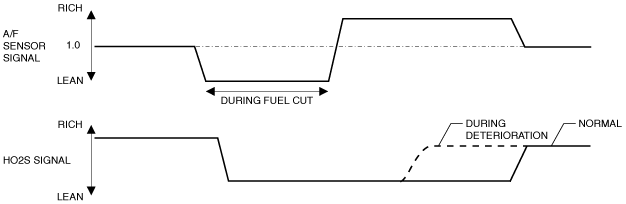
• The PCM compares the number of the A/F sensor and HO2S inversions for a predetermined time to detect the inversion ratio. It does this by monitoring the HO2S inversion counts when the following conditions are met. If the inversion ratio is below specification, the PCM determine that the catalyst system has deteriorated.
Diagnostic support note
• This is an intermittent monitor (catalyst).
• The check engine light illuminates if the PCM detects the above malfunction condition in two consecutive drive cycles or in one drive cycle while the DTC for the same malfunction has been stored in the PCM.
• PENDING CODE is available if the PCM detects the above malfunction condition during first drive cycle.
• FREEZE FRAME DATA (Mode 2)/Snapshot data is available.
• DTC is stored in the PCM memory.
|
|
FAIL-SAFE FUNCTION
|
Not applicable
|
|
POSSIBLE CAUSE
|
• Exhaust system leakage
• A/F sensor loose
• HO2S loose
• WU-TWC deterioration or malfunction
• PCM malfunction
|
|
SYSTEM WIRING DIAGRAM
|
Not applicable
|
Diagnostic Procedure
|
STEP |
INSPECTION |
ACTION |
|
|---|---|---|---|
|
1
|
VERIFY FREEZE FRAME DATA (MODE 2)/SNAPSHOT DATA AND DIAGNOSTIC MONITORING TEST RESULTS HAVE BEEN RECORDED
• Have the FREEZE FRAME DATA (Mode 2)/snapshot data and DIAGNOSTIC MONITORING TEST RESULTS (catalyst related) been recorded?
|
Yes
|
Go to the next step.
|
|
No
|
Record the FREEZE FRAME DATA (Mode 2)/snapshot data and DIAGNOSTIC MONITORING TEST RESULTS on the repair order, then go to the next step.
|
||
|
2
|
VERIFY RELATED SERVICE INFORMATION AVAILABILITY
• Verify related Service Information availability.
• Is any related Service Information available?
|
Yes
|
Perform repair or diagnosis according to the available Service Information.
• If the vehicle is not repaired, go to the next step.
|
|
No
|
Go to the next step.
|
||
|
3
|
VERIFY RELATED PENDING CODE AND/OR DTC
• Switch the ignition off, then ON (engine off).
• Perform the Pending Trouble Code Access Procedure and DTC Reading Procedure.
• Are any other PENDING CODEs and/or DTCs present?
|
Yes
|
Go to the applicable PENDING CODE or DTC inspection.
|
|
No
|
Go to the next step.
|
||
|
4
|
INSPECT EXHAUST SYSTEM FOR LEAKAGE
• Visually inspect for exhaust leakage in the exhaust system.
• Is there any leakage?
|
Yes
|
Repair or replace the malfunctioning part according to the inspection results, then go to Step 7.
|
|
No
|
Go to the next step.
|
||
|
5
|
INSPECT INSTALLATION OF A/F SENSOR AND HO2S
• Inspect installation of A/F sensor and HO2S.
• Are the A/F sensor and HO2S installed securely?
|
Yes
|
Go to the next step.
|
|
No
|
Retighten the A/F sensor and/or HO2S, then go to Step 7.
|
||
|
6
|
VERIFY WHETHER MALFUNCTION IS IN WU-TWC OR ELSEWHERE
• Perform the Idle Mixture Inspection.
• Is there any malfunction?
|
Yes
|
Perform the symptom troubleshooting “NO.15 EMISSION COMPLIANCE”.
• If there is any malfunction:
• If there is no malfunction:
Go to the next step.
|
|
No
|
Go to the next step.
|
||
|
7
|
VERIFY DTC TROUBLESHOOTING COMPLETED
• Always reconnect all disconnected connectors.
• Clear the DTC from the PCM memory using the M-MDS.
• Perform the Drive Mode 03 (Variable Valve Timing, A/F Sensor Heater, HO2S Heater, A/F Sensor, HO2S and WU-TWC Repair Verification Drive Mode).
• Is the PENDING CODE for this DTC present?
|
Yes
|
Repeat the inspection from Step 1.
• If the malfunction recurs, replace the PCM.
Go to the next step.
|
|
No
|
Go to the next step.
|
||
|
8
|
VERIFY AFTER REPAIR PROCEDURE
• Perform the “AFTER REPAIR PROCEDURE”.
• Are any DTCs present?
|
Yes
|
Go to the applicable DTC inspection.
|
|
No
|
DTC troubleshooting completed.
|
||
SKYACTIV-G 2.0 (ATX), SKYACTIV-G 2.5
Details On DTCs
|
DESCRIPTION |
Catalytic converter system |
|
|---|---|---|
|
DETECTION CONDITION
|
Determination conditions
|
• The PCM detects that the HO2S output fluctuates from lean to rich in a short amount of time at specified times continuously after recovery from fuel cut control.
|
|
Preconditions
|
• Catalytic converter (WU-TWC) is activated sufficiently.
• HO2S is activated sufficiently.
• The following DTCs are not detected:
|
|
|
Drive cycle
|
• 2
|
|
|
Self test type
|
• CMDTC self test
|
|
|
Sensor used
|
• A/F sensor, HO2S
|
|
|
FAIL-SAFE FUNCTION
|
• Not applicable
|
|
|
VEHICLE STATUS WHEN DTCs ARE OUTPUT
|
• Illuminates check engine light.
|
|
|
POSSIBLE CAUSE
|
• HO2S malfunction
• A/F sensor malfunction
• WU-TWC deterioration or malfunction
• PCM malfunction
|
|
System Wiring Diagram
Function Explanation (DTC Detection Outline)
ac5wzw00007180
|
Repeatability Verification Procedure
PID Item/Simulation Item Used In Diagnosis
PID/DATA monitor item table
|
Item |
Definition |
Unit/Condition |
Condition/Specification (Reference) |
|---|---|---|---|
|
O2S11
|
A/F sensor
|
µA
|
• Idle (after warm up): Approx. -39 µA
• Deceleration fuel cut (accelerator pedal released from engine speed of 4,000 rpm or more): Approx. 3.84 mA
|
|
O2S12
|
HO2S
|
V
|
• Idle (after warm up): 0—1.0 V
• Deceleration fuel cut (accelerator pedal released from engine speed of 4,000 rpm or more): Approx. 0 V
|
Function Inspection Using M-MDS
|
STEP |
INSPECTION |
RESULTS |
ACTION |
|---|---|---|---|
|
1
|
PURPOSE: VERIFY RELATED SERVICE INFORMATION AVAILABILITY
• Verify related Service Information availability.
• Is any related Service Information available?
|
Yes
|
Perform repair or diagnosis according to the available Service Information.
• If the vehicle is not repaired, go to the next step.
|
|
No
|
Go to the next step.
|
||
|
2
|
PURPOSE: IDENTIFY TRIGGER DTC FOR FREEZE FRAME DATA (MODE 2)
• Is the DTC P0421:00 on FREEZE FRAME DATA (Mode 2)?
|
Yes
|
Go to the next step.
|
|
No
|
Go to the troubleshooting procedure for DTC on FREEZE FRAME DATA (Mode 2).
|
||
|
3
|
PURPOSE: RECORD VEHICLE STATUS AT TIME OF DTC DETECTION TO UTILIZE WITH REPEATABILITY VERIFICATION
• Has the FREEZE FRAME DATA (Mode 2)/snapshot data been recorded?
|
Yes
|
Go to the next step.
|
|
No
|
Record the FREEZE FRAME DATA (Mode 2)/snapshot data on the repair order, then go to the next step.
|
||
|
4
|
PURPOSE: VERIFY RELATED PENDING CODE AND/OR DTC
• Switch the ignition off, then ON (engine off).
• Perform the Pending Trouble Code Access Procedure and DTC Reading Procedure.
• Are any other PENDING CODEs and/or DTCs present?
|
Yes
|
Go to the applicable PENDING CODE or DTC inspection.
Go to the next step.
|
|
No
|
Go to the next step.
|
||
|
5
|
PURPOSE: VERIFY A/F SENSOR AND HO2S INPUT SIGNAL
• Start the engine and warm it up completely.
• Access the following PIDs using the M-MDS:
• Drive the vehicle under the following conditions.
• Is the displayed PID value as follows?
|
Yes
|
Go to the troubleshooting procedure to perform the procedure from Step 3.
|
|
No
|
Go to the next step.
|
||
|
6
|
INSPECT RELATED SENSOR WIRING HARNESS AND CONNECTOR
• Access the following PIDs using the M-MDS:
• When the PCM, A/F sensor and HO2S are shaken, does the PID value include a PID item which has changed?
|
Yes
|
Inspect the related wiring harness and connector.
• Repair or replace the malfunctioning part.
Go to the troubleshooting procedure to perform the procedure from Step 8.
|
|
No
|
Go to the troubleshooting procedure to perform the procedure from Step 1.
|
Troubleshooting Diagnostic Procedure
|
STEP |
INSPECTION |
RESULTS |
ACTION |
|---|---|---|---|
|
1
|
PURPOSE: INSPECT INSTALLATION OF HO2S
• Inspect installation of HO2S.
• Is the HO2S installed securely?
|
Yes
|
Go to the next step.
|
|
No
|
Retighten the HO2S, then go to Step 8.
|
||
|
2
|
PURPOSE: INSPECT INSTALLATION OF A/F SENSOR
• Inspect installation of A/F sensor.
• Is the A/F sensor installed securely?
|
Yes
|
Replace the A/F sensor and/or HO2S, then go to Step 8.
|
|
No
|
Retighten the A/F sensor, then go to Step 8.
|
||
|
3
|
PURPOSE: INSPECT INSTALLATION OF HO2S
• Inspect installation of HO2S.
• Is the HO2S installed securely?
|
Yes
|
Go to the next step.
|
|
No
|
Retighten the HO2S, then go to Step 8.
|
||
|
4
|
PURPOSE: INSPECT INSTALLATION OF A/F SENSOR
• Inspect installation of A/F sensor.
• Is the A/F sensor installed securely?
|
Yes
|
Go to the next step.
|
|
No
|
Retighten the A/F sensor, then go to Step 8.
|
||
|
5
|
PURPOSE: INSPECT EXHAUST SYSTEM FOR LEAKAGE
• Visually inspect for exhaust gas leakage from the exhaust system.
• Is there any malfunction?
|
Yes
|
Repair or replace the malfunctioning part according to the inspection results, then go to Step 8.
|
|
No
|
Go to the next step.
|
||
|
6
|
PURPOSE: VERIFY IF OTHER DTCs ARE DISPLAYED
• Reconnect all disconnected connectors.
• Clear the DTC from the PCM memory using the M-MDS.
• Implement the repeatability verification procedure.
• Perform the Pending Trouble Code Access Procedure and DTC Reading Procedure.
• Are any other PENDING CODEs and/or DTCs present?
|
Yes
|
Go to the applicable PENDING CODE or DTC inspection.
Go to the next step.
|
|
No
|
Go to the next step.
|
||
|
7
|
PURPOSE: VERIFY CATALYTIC CONVERTER (WU-TWC) MALFUNCTION
• Clear the DTC from the PCM memory using the M-MDS.
• Implement the repeatability verification procedure.
• Perform the Pending Trouble Code Access Procedure.
• Is the PENDING CODE for this DTC present?
|
Yes
|
Replace the exhaust manifold, then go to the next step.
|
|
No
|
DTC troubleshooting completed.
|
||
|
8
|
PURPOSE: VERIFICATION OF VEHICLE REPAIR COMPLETION
• Always reconnect all disconnected connectors.
• Clear the DTC from the PCM memory using the M-MDS.
• Implement the repeatability verification procedure.
• Perform the Pending Trouble Code Access Procedure.
• Is the PENDING CODE for this DTC present?
|
Yes
|
Repeat the inspection from Step 1.
• If the malfunction recurs, replace the PCM.
Go to the next step.
|
|
No
|
Go to the next step.
|
||
|
9
|
PURPOSE: VERIFY IF THERE IS ANY OTHER MALFUNCTION
• Is any other DTC or pending code stored?
|
Yes
|
Go to the applicable DTC inspection.
|
|
No
|
DTC troubleshooting completed.
|