PCM REMOVAL/INSTALLATION [SKYACTIV-D 2.2]
id0140z7802400
-
Caution
-
• To prevent the A/F sensor damage, do not perform the following operation before starting the engine for the first time after the PCM is replaced.
-
― Fully depress and release the accelerator pedal three times repeatedly while depressing the brake pedal with the switch the ignition ON.
-
Note
-
• If the PCM is replaced, perform the “PCM Replacement”.
Procedure For PCM Replacement
-
Note
-
• The PCM replacement differs depending on whether As-built data is used or not during the PCM configuration.
Replacement procedure determination
|
Step
|
Action
|
Results
|
Action
|
|
1
|
Is the cause of the PCM replacement a malfunction in the PCM?
|
Yes
|
Go to Step 6.
|
|
No
|
Go to the next step.
|
|
2
|
Verify the suffix of the PCM file names on the log viewer verification screen of the M-MDS.
|
D or E (Except Australian specs.)
D, E or F (Australian specs.)
|
Go to the next step.
|
|
After F (Except Australian specs.)
After G (Australian specs.)
|
Go to Step 6.
|
|
3
|
Perform PCM reprogramming.
-
Note
-
• CAN related DTCs (U****:**) are stored by performing PCM reprogramming.
|
—
|
Go to the next step.
|
|
4
|
Switch the ignition off and then switch it ON (engine off) again.
|
—
|
Go to the next step.
|
|
5
|
Clear CAN related DTCs (U****:**).
|
—
|
Go to the next step.
|
|
6
|
Perform the PCM configuration and verify if the As-Built data input screen is displayed or not.
|
Not displayed
|
Go to “Procedure for PCM replacement (pattern 1)”.
|
|
Displayed
|
Go to “Procedure for PCM replacement (pattern 2)”.
|
Procedure for PCM replacement (pattern 1)
|
Step
|
Action
|
Page
|
|
1
|
Continue to perform the configuration.
|
—
|
|
2
|
Clear the DTCs.
|
|
|
3
|
Wait for 20 s or more.
|
—
|
|
4
|
Perform the immobilizer system-related part programming.
|
|
|
5
|
Perform the KOEO self test.
|
|
|
6
|
Perform the KOER self test.
|
|
|
7
|
Perform the fuel injection amount correction.
|
|
|
8
|
Perform the battery condition initial setting (i-stop setting).
|
|
Procedure for PCM replacement (pattern 2)
|
Step
|
Action
|
Page
|
|
1
|
Perform the configuration using the As-Built data.
|
|
|
2
|
Store the identification number of the fuel injector equipped to the vehicle.
|
—
|
|
3
|
Perform the fuel injector code programming.
|
|
|
4
|
Perform the PCM data reset.
|
|
|
5
|
Perform the immobilizer system-related part programming.
|
|
|
6
|
Clear the DTCs.
|
|
|
7
|
Wait for 20 s or more.
|
—
|
|
8
|
Perform the KOEO self test.
|
|
|
9
|
Perform the KOER self test.
|
|
|
10
|
Perform the fuel injection amount correction.
|
|
|
11
|
Perform compulsory diesel particulate filter regeneration.
|
|
|
12
|
Perform the following procedure:
1. Warm up the engine until the engine coolant temperature is 70 °C {158 °F} or more.
2. Switch the ignition off.
3. Store “Complete (delete record)” the M-MDS session.
4. Remove the M-MDS.
5. Start the engine.
6. Leave for 3 min while idling.
7. Continuously drive the vehicle for 30 s at a vehicle speed of 50 km/h {31 mph} or more.
-
― When the warning light turns on or flashes, repeat the procedure from Step 5 (start the engine).
8. After stopping the vehicle, leave it idling for 3 min without stopping the engine.
9. Continuously drive the vehicle for 30 s at a vehicle speed 50 km/h {31 mph} or more again.
-
― When the warning light turns on or flashes, repeat the procedure from Step 5 (start the engine).
|
—
|
|
13
|
Verify that the learning value (O2S11_CAL) for the A/F sensor is other than 0.
• If the learning value (02S11_CAL) for the A/F sensor is 0, repeat the procedure from Step 5 (start the engine).
|
—
|
|
14
|
Clear the DTCs.
|
|
|
15
|
Replace the engine oil.
-
Note
-
• Because the PCM is new, it is not necessary to perform the engine oil data reset.
|
|
|
16
|
Perform the battery condition initial setting (i-stop setting).
|
|
PCM Removal/Installation
Without set bolt
1. Disconnect the negative battery cable. (See NEGATIVE BATTERY CABLE DISCONNECTION/CONNECTION [SKYACTIV-D 2.2].)
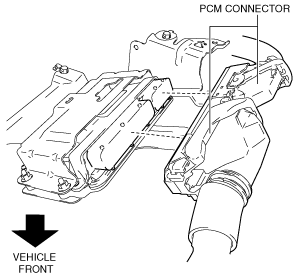
2. Disconnect the PCM connectors. (See Set Bolt Installation Note.)
3. Remove clip A from the PCM bracket.
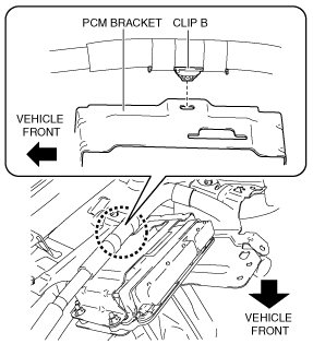
4. Remove clip B from the PCM bracket.
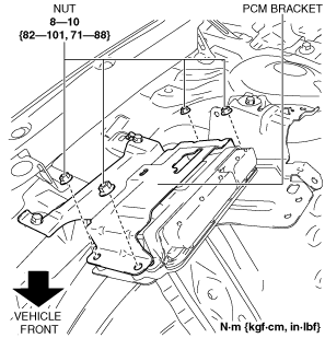
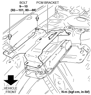
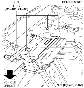
5. Remove the nuts from the PCM bracket.
6. Remove the PCM bracket. (See Without set bolt.)
7. Remove the PCM.
8. Install in the reverse order of removal.
9. When replacing the PCM on the vehicles, perform the “Procedure For PCM Replacement”. (See Procedure For PCM Replacement.)
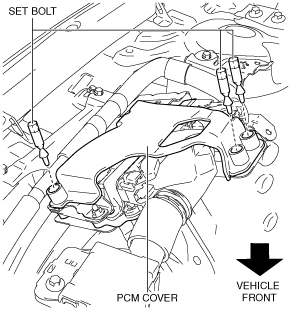
With set bolt
1. Disconnect the negative battery cable. (See NEGATIVE BATTERY CABLE DISCONNECTION/CONNECTION [SKYACTIV-D 2.2].)
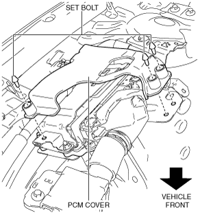
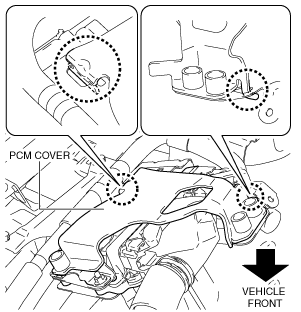
2. Remove the PCM cover. (See With set bolt.) (See PCM Bracket Installation Note.) (See Set Bolt Removal Note.)
3. Disconnect the PCM connectors. (See Set Bolt Installation Note.)
4. Remove clip A from the PCM bracket.
5. Remove clip B from the PCM bracket.
6. Remove the nuts from the PCM bracket.
7. Remove the PCM bracket. (See Without set bolt.)
8. Remove the PCM.
9. Install in the reverse order of removal.
10. When replacing the PCM on the vehicles, perform the “Procedure For PCM Replacement”. (See Procedure For PCM Replacement.)
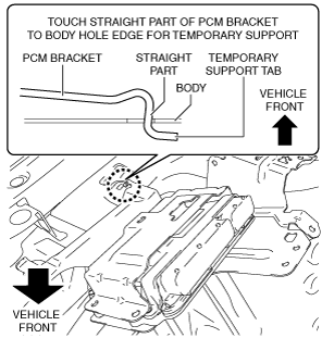
PCM Bracket Installation Note
1. Install the PCM bracket as shown in the figure.
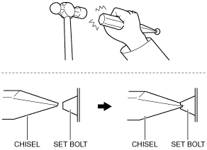
Set Bolt Removal Note
1. Using a chisel and a hammer, cut a groove on the head of the set bolt so that a screwdriver can be inserted.
2. Loose the set bolt using an impact screwdriver or pliers.
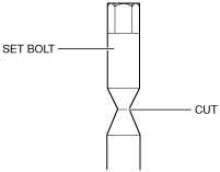
Set Bolt Installation Note
1. Install a new set bolt and tighten it until the neck of the bolt is cut.
PCM Cover Installation Note
1. Install the PCM cover as shown in the figure.
2. Temporarily tighten the three bolts, then completely tighten them.
PCM Connector Connection Note
-
Caution
-
• Do not touch the PCM connector terminal. The terminal is extremely thin and can be damaged by touching it.
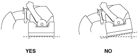
• If the PCM connector is inserted at an angle and the lever is moved, the connector could be damaged. Verify that the PCM connector is inserted straight.
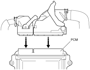
1. Set the PCM connector to the position shown in the figure.
2. Align the PCM connector straight against the connection surface.
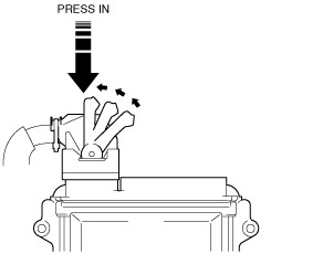
3. Insert the PCM connector straight and press it in until the lever moves up naturally. (Front harness-side connector)
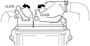
4. Press the PCM connector lever until a click sound is heard.