|
1
|
VERIFY IF LEFT AND RIGHT BSM CONTROL MODULES ARE INSTALLED IN REVERSE
• Verify that the left and right indication labels are attached to the BSM control modules.
• Are the left and right BSM control modules installed correctly?
|
Yes
|
Go to the next step.
|
|
No
|
Install the BSM control modules in their proper positions, then go to Step 6.
|
|
2
|
INSPECT BSM CONTROL MODULE (LH) CONNECTOR CONDITION
• Switch the ignition to off.
• Disconnect the negative battery cable.
• Disconnect the BSM control module (LH) connector.
• Inspect the connector engagement and connection condition and inspect the terminals for damage, deformation, corrosion, or disconnection.
• Is the connector normal?
|
Yes
|
Go to the next step.
|
|
No
|
Repair or replace the connector, then go to Step 6.
|
|
3
|
INSPECT BSM CONTROL MODULE (LH) CIRCUIT FOR OPEN CIRCUIT
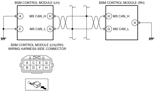
• Verify that the BSM control module (LH) connector is disconnected.
• Inspect the wiring harness between the following terminals (vehicle wiring harness side) and body ground for continuity.
-
― BSM control module (LH) terminal A
― BSM control module (LH) terminal E
• Is there continuity?
|
Yes
|
Go to the next step.
|
|
No
|
Repair or replace the wiring harness which has an open circuit, then go to Step 6.
|
|
4
|
INSPECT BSM CONTROL MODULE (RH) CONNECTOR CONDITION
• Disconnect the BSM control module (RH) connector.
• Inspect the connector engagement and connection condition and inspect the terminals for damage, deformation, corrosion, or disconnection.
• Is the connector normal?
|
Yes
|
Go to the next step.
|
|
No
|
Repair or replace the connector, then go to Step 6.
|
|
5
|
INSPECT BSM CONTROL MODULE (RH) CIRCUIT FOR OPEN CIRCUIT
• Verify that the BSM control module (RH) connector is disconnected.
• Inspect for continuity between BSM control module (RH) terminal A (vehicle wiring harness side) and body ground.
• Is there continuity?
|
Yes
|
Go to the next step.
|
|
No
|
Repair or replace the wiring harness which has an open circuit, then go to the next step.
|
|
6
|
VERIFY THAT REPAIRS HAVE BEEN COMPLETED
• Reconnect all the disconnected connectors.
• Reconnect the disconnected negative battery cable.
• Clear BSM control module DTCs using the M-MDS.
• Perform the DTC inspection for the BSM control module using the M-MDS.
• Is DTC U3000:4A displayed?
|
Yes
|
Repeat the inspection from Step 1.
• If the malfunction recurs, replace the BSM control module, then go to the next step.
|
|
No
|
Go to the next step.
|
|
7
|
VERIFY IF OTHER DTCs DISPLAYED
• Are any other DTCs displayed?
|
Yes
|
Repair the malfunctioning part according to the applicable DTC troubleshooting.
|
|
No
|
DTC troubleshooting completed.
|