|
1
|
INSPECT IF MALFUNCTION CAUSE IS START STOP UNIT OR FRONT BODY CONTROL MODULE (FBCM)
• Display start stop unit PID H/L_SW_LOW using the M-MDS.
• Verify the PID while operating the light switch.
• Is the display of PID H/L_SW_LOW normal?
|
Yes
|
Go to Step 3.
|
|
No
|
Go to the next step.
|
|
2
|
INSPECT LIGHT SWITCH
• Inspect the light switch.
• Is the light switch normal?
|
Yes
|
Replace the start stop unit, then go to Step 7.
|
|
No
|
Replace the light switch, then go to Step 7.
|
|
3
|
INSPECT IF MALFUNCTION CAUSE IS FRONT BODY CONTROL MODULE (FBCM) OR WIRING HARNESS
• Display front body control module (FBCM) PID H/L_SW_LOW1 using the M-MDS.
• Verify the PID while operating the light switch.
• Is the display of PID H/L_SW_LOW1 normal?
|
Yes
|
Go to the next step.
|
|
No
|
• Perform the CAN malfunction diagnosis flow and inspect the CAN for a malfunction.
• If there is no malfunction in CAN, replace the front body control module (FBCM), then go to Step 7.
|
|
4
|
INSPECT FOR SHORT TO GROUND BETWEEN LIGHT SWITCH AND FRONT BODY CONTROL MODULE (FBCM)
• Switch the light switch off.
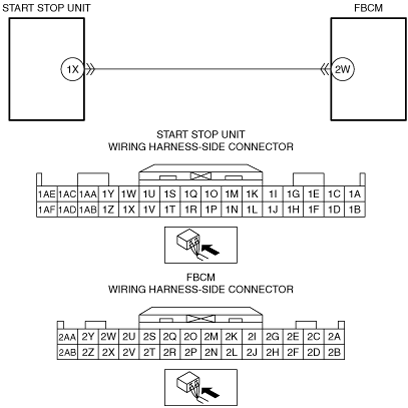
• Inspect for continuity between front body control module (FBCM) terminal 2W and body ground.
• Is there continuity?
|
Yes
|
Repair or replace the wiring harness, then go to Step 7.
|
|
No
|
Go to the next step.
|
|
5
|
INSPECT WIRING HARNESS BETWEEN LIGHT SWITCH AND FRONT BODY CONTROL MODULE (FBCM) FOR OPEN CIRCUIT
• Disconnect the front body control module (FBCM) connector.
• Disconnect the start stop unit connector.
• Inspect for continuity between front body control module (FBCM) terminal 2W and start stop unit terminal 1X.
• Is there continuity?
|
Yes
|
Go to the next step.
|
|
No
|
Repair or replace the wiring harness, then go to Step 7.
|
|
6
|
INSPECT FOR SHORT TO POWER SUPPLY BETWEEN LIGHT SWITCH AND FRONT BODY CONTROL MODULE (FBCM)
• Verify that the start stop unit and front body control module (FBCM) connectors are disconnected.
• Connect the negative battery cable.
• Switch the ignition ON (engine off or on).
• Measure the voltage at front body control module (FBCM) terminal 2W.
• Is the voltage 0 V?
|
Yes
|
Go to the next step.
|
|
No
|
Repair or replace the wiring harness and go to the next step.
|
|
7
|
VERIFY THAT REPAIRS HAVE BEEN COMPLETED
• Clear front body control module (FBCM) DTCs using the M-MDS.
• Switch the ignition ON (engine off or on) and wait for 5 s or more.
• Perform the front body control module (FBCM) DTC inspection using the M-MDS.
• Is DTC B13AF:62 displayed?
|
Yes
|
Replace the front body control module (FBCM), then go to the next step.
|
|
No
|
Go to the next step.
|
|
8
|
VERIFY IF OTHER DTCs DISPLAYED
• Are any other DTCs displayed?
|
Yes
|
Repair the malfunctioning part according to the applicable DTC troubleshooting.
|
|
No
|
DTC troubleshooting completed.
|